RAS Know-how Knowledge in a nutshell

Was ist eigentlich Schwenkbiegen?
Bei welchen Biegeteilen eignet sich Schw...
Schnelles Rüsten
Einfaches Handling
UpDown-Schwenkbiegen mit Pendeln und Umf...
UpDown-Schwenkbiegen mit einer oder zwei...
Radien biegen
Schwenkbiegen von Edelstahl und beschich...
Schwenkbiegen von Lochblech, Streckgitte...
Frequently Asked Questions About Press Brakes, Die Bending and Swivel Bending
Answers to the most important questions about sheet metal bending processes, from the basics through to the RAS machines.
Basics
A press brake, also called a die bending machine, is a machine tool for bending sheet metal. A ram fitted with an upper tool (punch) moves down and presses the sheet into a V-shaped die. This creates the bend angle. The process is also known as die bending and is one of the most widely used sheet metal bending methods.
There is no real difference. Press brake is the name of the machine, die bending is the name of the process carried out on that machine. Both terms describe the same operation: a punch presses the sheet into a V die.
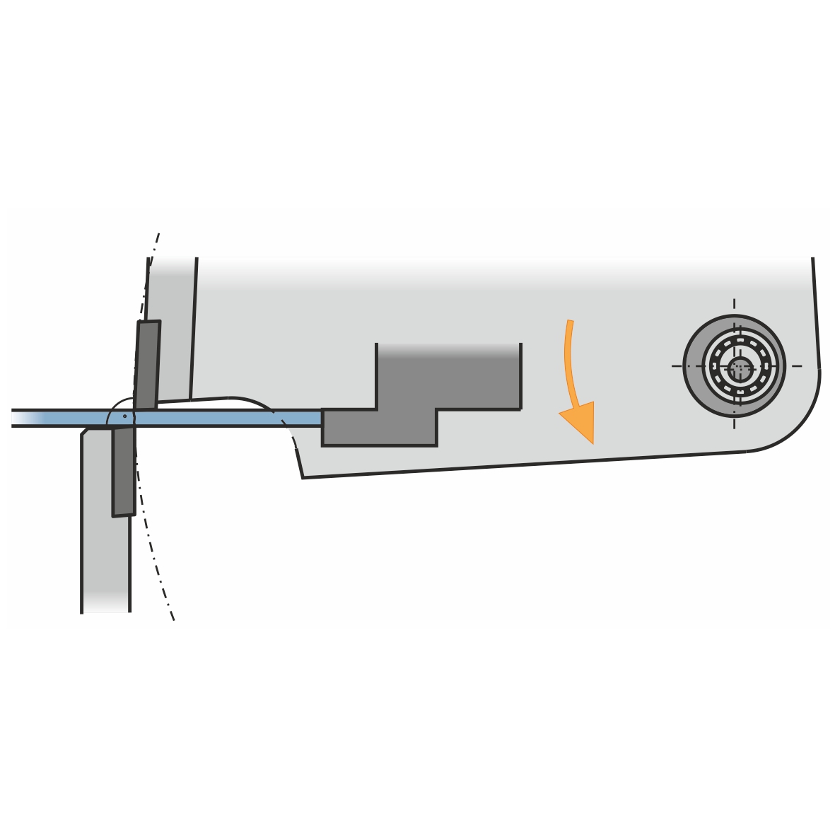
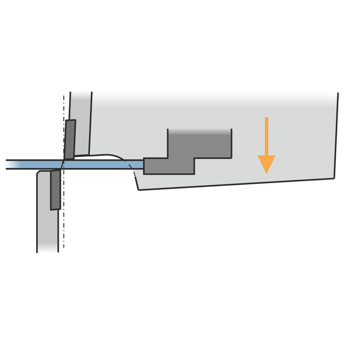
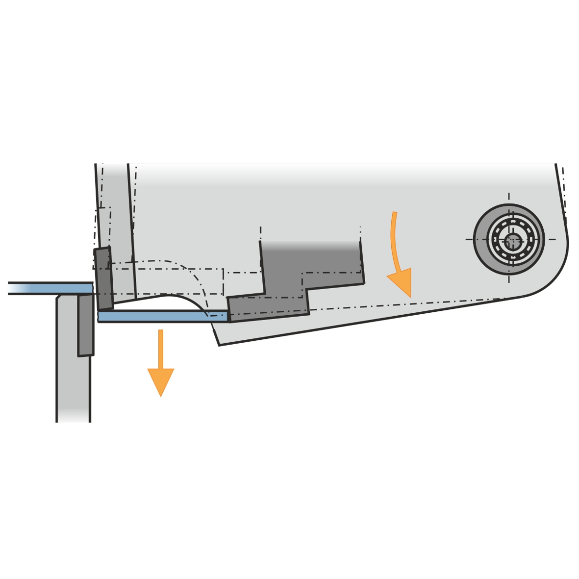
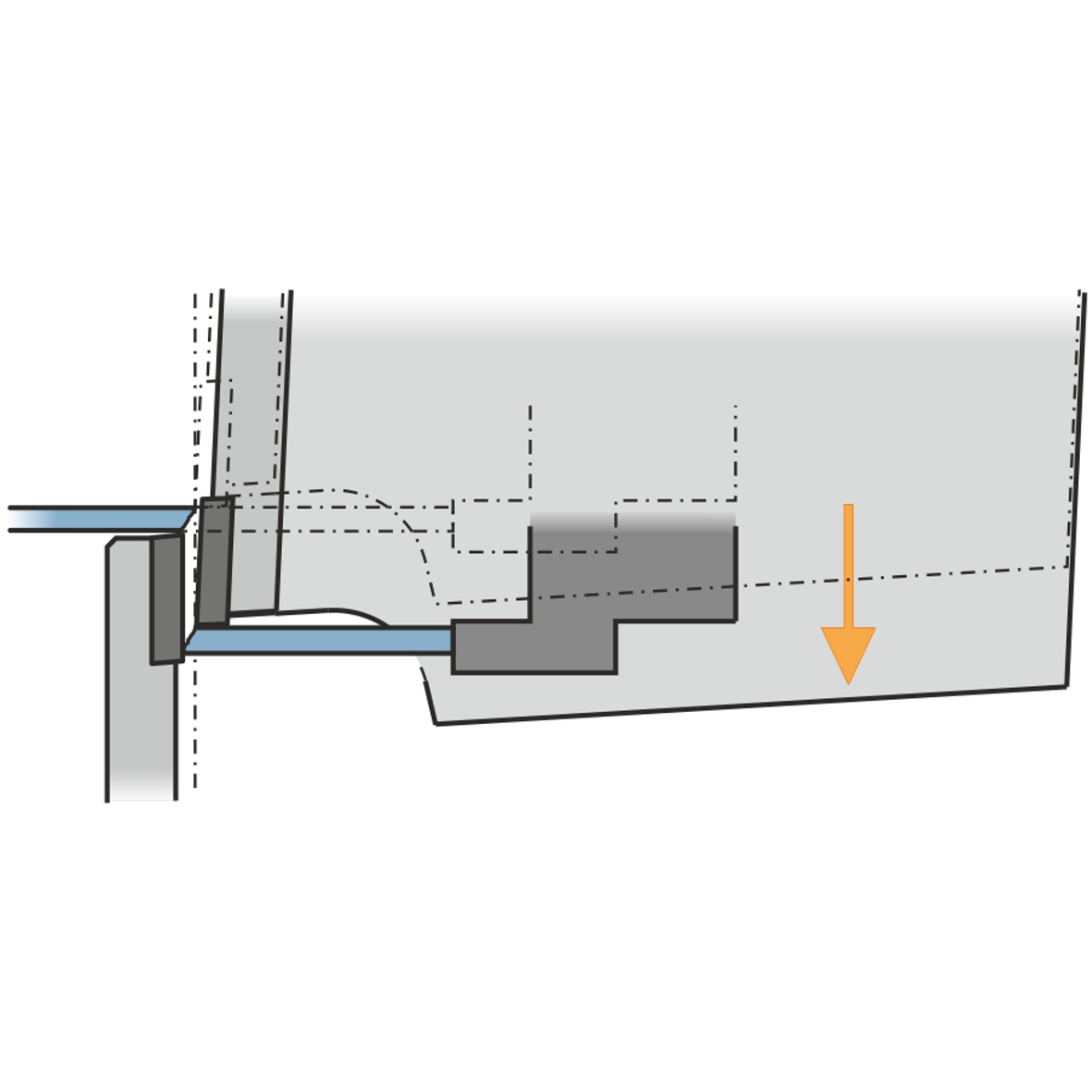
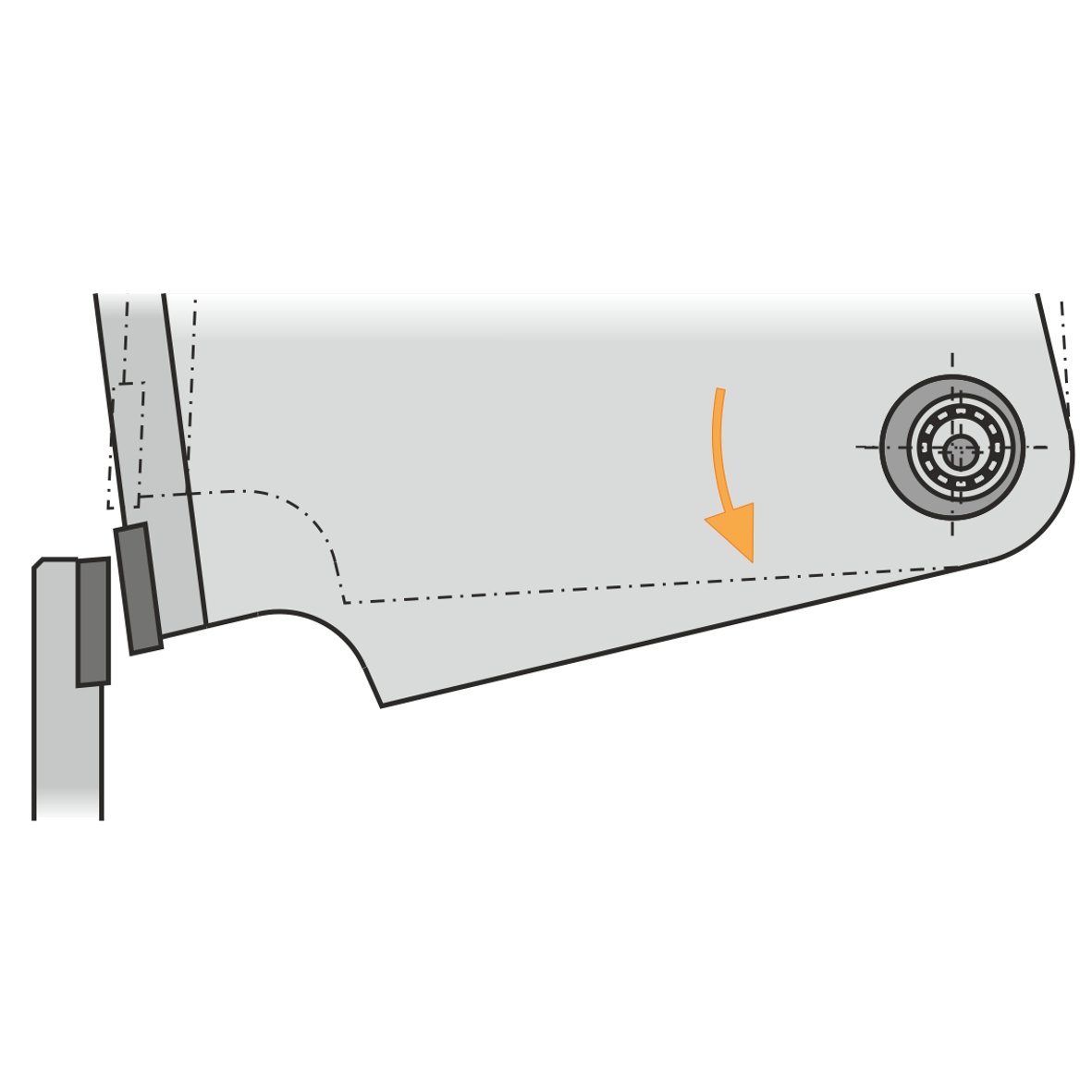
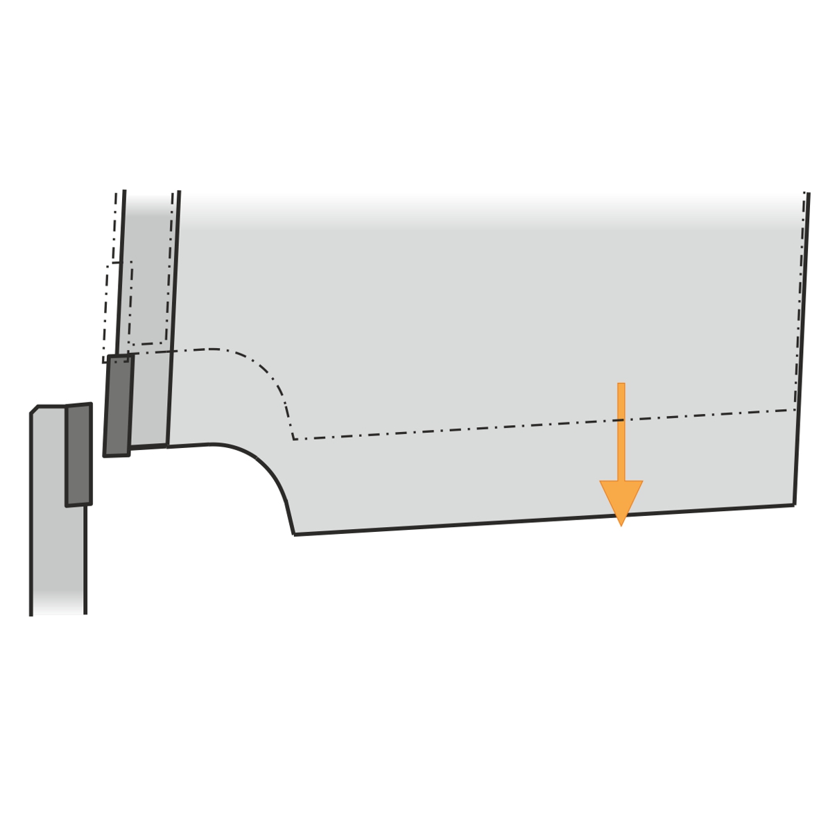
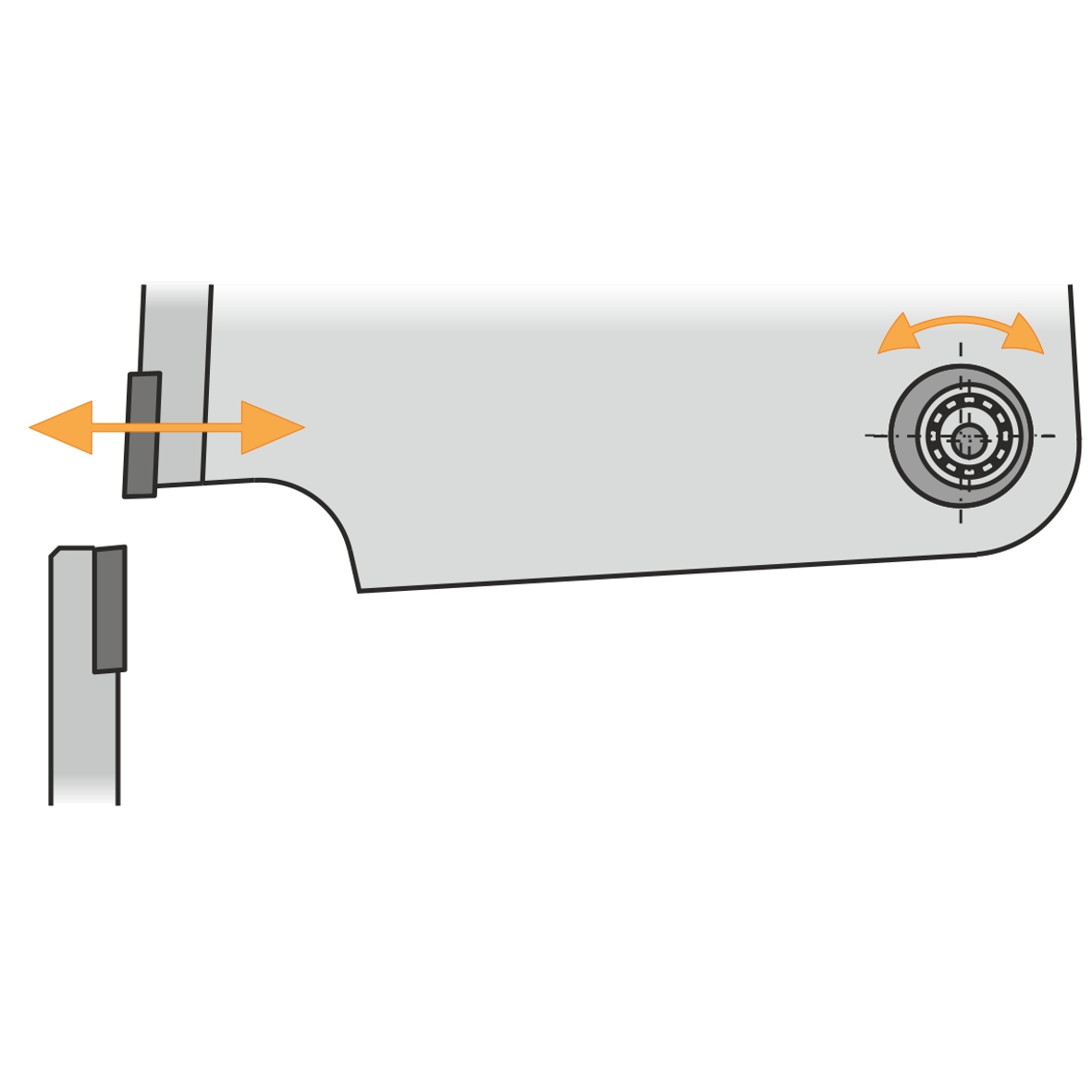
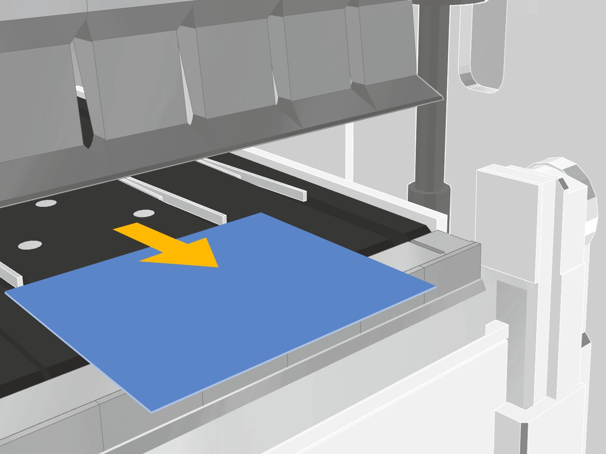
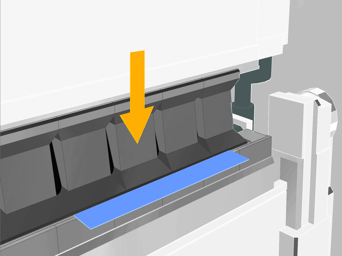
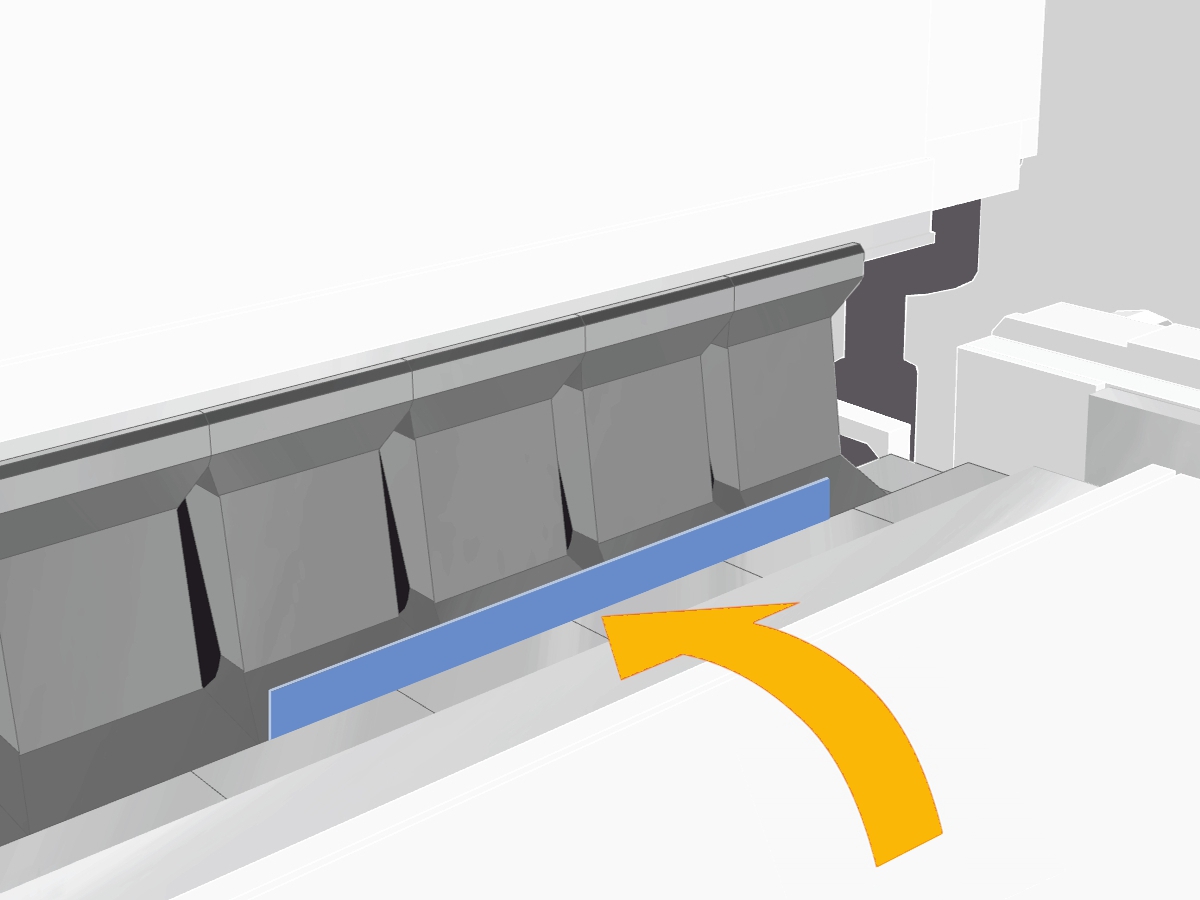
Swivel bending is a sheet metal bending process in which the sheet stays on a table and is clamped between the upper and lower beam. A folding beam pivots up or down around a fixed point to create the bend angle, while the part itself stays in place. Unlike die bending, the operator does not need to lift or guide the sheet during the bending cycle.
Folding is the common term for bending sheet metal on a press brake, i.e. for die bending. In practice, the term is often used interchangeably with die bending or sheet metal bending, though technically it refers specifically to the process carried out on a press brake.
In swivel bending, the sheet is firmly clamped between the upper and lower beam. The folding beam then pivots along the projecting leg upward or downward until the programmed angle is reached. The sheet itself does not move, only the tool performs the pivoting motion. This is fundamentally different from die bending, where the sheet moves into a tool.
The name swivel bending describes the characteristic motion of the process: a folding beam pivots around a fixed point instead of moving in a straight line into a tool, as in die bending. This pivoting motion creates the bend angle and gives the process its name.
Swivel bending machines have existed since the late 1940s. RAS Reinhardt Maschinenbau brought one of the first swivel bending machines to market shortly after its incorporation in 1948, and added a hydraulic version in 1954. In 1968, RAS introduced the world's first NC-controlled swivel bending machine, an important step toward today's CNC-controlled technology.
Swivel bending offers high angular accuracy, low tool wear and a much more scratch-free process, since the sheet barely slides over any tool edges during bending. It also brings short setup times through universal tools, more ergonomic operation because the part stays on the table, and the ability to combine several operations such as beading or hemming in a single setup.
Swivel bending machines are usually more expensive to purchase than comparable press brakes, an investment that pays off over time through shorter setup times, less scrap and lower tool wear. There are also geometric limits for very complex, deep-drawn formed parts, for which other forming processes may be better suited.
Swivel bending reaches its limits with very complex, deep-drawn parts with free-form surfaces, with extremely thick sheets beyond the capacity of available swivel bending machines, and with geometries that can be produced more economically with other forming processes. For very high quantities of an unchanging, simple part, a dedicated press brake can also remain competitive in pure cycle time.
Parts that are not, or only partly, suited to swivel bending include components with true free-form surfaces and deep-drawn geometries, very small radii below the capability of available tools, extremely thick sheets beyond machine capacity, and geometries that can only be produced by localized forming processes such as coining or stretch forming.
Swivel bending machines achieve tight angular tolerances because the tool engages the outside of the sheet and pivots precisely to the programmed angle, so sheet thickness tolerances have almost no effect. Additional systems such as automatic angle measurement and intelligent crowning further compensate for material variation along the entire bending length.
How swivel bending works in detail
The sheet is clamped between the upper and lower beam so that the leg to be bent projects freely over the tool edge. The folding beam pivots around a fixed point along this edge, pressing the projecting leg up or down and forming the bend angle, without the sheet itself moving through the machine.
During bending, the material is stretched on the outside of the bend and compressed on the inside. In between lies the so-called neutral fiber, which keeps its original length. If the stretching exceeds the material's capacity, cracks or micro-cracks can form on the outside of the bend edge, especially with too small a bend radius or an unfavorable rolling direction.
Material springs back because bending produces not only plastic, i.e. permanent, deformation but also elastic deformation. As soon as the bending force is removed, part of the elastic deformation reverses, so the finished angle ends up slightly larger than the one set. How much a material springs back depends on the material, sheet thickness and bend radius, and is compensated mathematically in modern bending machines and their software.
The bend angle is determined mainly by the pivoting travel of the folding beam, the sheet thickness, the material and its springback behavior. The rolling direction of the sheet and the tools used also affect the result. Modern swivel bending machines take these factors into account automatically and adjust the pivoting travel accordingly to reach the programmed target angle.
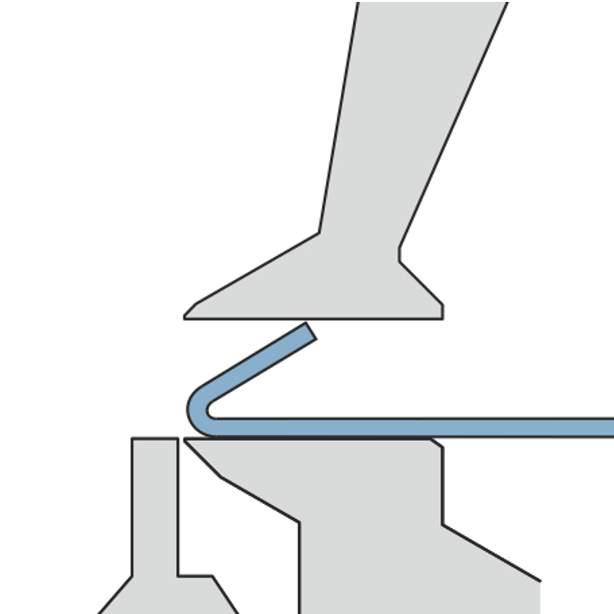
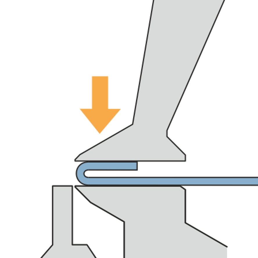
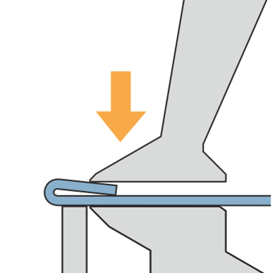
A hem is created when a sheet leg is bent back 180 degrees so that two layers of sheet lie on top of each other. In swivel bending this is done in several steps, with the folding beam gradually folding the leg further over until the two layers lie flat or with a defined gap on top of each other.
Tight radii are produced through several short, consecutive bending steps with a small pivot angle that together form a smooth radius. For very tight or frequently recurring radii, special radius tools are additionally used, which form the radius in a single step.
Depending on the tooling, swivel bending machines cover angles from just a few degrees up to 180-degree hems. The usable angle range depends on the upper and lower beam tools used as well as any additional tools.
The achievable angular tolerances depend on the machine, material and part geometry, but are generally tighter with swivel bending machines than with classic die bending, since sheet thickness variation has almost no effect on the angle. For particularly tight tolerances, additional systems for automatic angle measurement and correction are available.
Because in swivel bending it is not the sheet but the tool that moves: the folding beam pivots around the sheet, which is clamped in a fixed position. This reduces the force the operator has to apply, improves ergonomics, and makes it possible for one person to handle even large or heavy sheet metal parts.
Swivel bending compared to die bending
In die bending, the sheet moves along because a punch presses it into a "V" die. The operator has to support and guide the workpiece. In swivel bending, the sheet stays on the table while a folding beam pivots around the material. This directly affects ergonomics, accuracy, setup time and surface quality. A detailed, illustrated comparison with videos is available in the RAS know-how section.
Swivel bending generally achieves higher angular accuracy, because the tool engages the outside of the sheet and pivots precisely to the programmed angle. Sheet thickness tolerances have almost no effect. In die bending, the punch contacts the sheet from above and the die from below. Thickness tolerances directly affect the bend angle, which is why additional angle measuring systems are often needed for compensation.
In die bending, the sheet slides over the edges of the "V" die. This long sliding distance shows up as visible scratches on the surface, especially with stainless steel or coated materials. Swivel bending machines reduce this sliding to a minimum, or eliminate it entirely on certain designs, which makes them better suited to sensitive surfaces.
Surfaces that are scratch-sensitive and visually demanding benefit most, such as stainless steel, brushed aluminum, powder-coated or pre-painted sheets, and already printed cosmetic parts, because swivel bending produces almost no relative movement between the tool and the sheet surface.
Swivel bending is superior to die bending above all when high angular accuracy is required over the entire bending length, when sensitive or pre-coated surfaces need to stay scratch-free, with frequently changing parts and small batch sizes, and with large or heavy sheets that should be handled ergonomically by a single operator.
Swivel bending machines bend most angles with a single, universal tool set and adjust automatically to the sheet thickness, which significantly shortens setup time. In die bending, different punches and "V" dies are needed for different sheet thicknesses and bending tasks, which leads to more frequent and longer setups with small batch sizes.
In die bending, the blank is positioned outside the machine and the operator has to hold and guide the weight of the sheet during the bending cycle. Large or heavy parts often require several operators, which can contribute to shoulder problems. In swivel bending, the part stays on the table. An upright posture is possible, and usually one operator is enough even for large parts.
Yes. In swivel bending, a radius can be built up from several short bending steps without the need for special tools. With a small step size, the individual bending steps are not visible on the outside. In die bending, creating radii with bending steps is much more complex, because the sheet lifts at each step. This leads to long bending times and high demands on the operator.
Yes. In die bending, the long sliding distances of the sheet over the die edges lead to tool wear. Bending results can deteriorate over time and bending programs need to be readjusted. In swivel bending there is only slight relative movement between tool and material. The tools show almost no abrasion wear even after years of use.
For individual, simple bends in high quantities, die bending can be comparably fast in pure cycle time. As soon as parts require several different angles, tool changes or varying batch sizes, swivel bending is usually faster in overall throughput thanks to shorter setup times and universal tools.
It depends on the part mix. For high quantities of an always identical, simple part, a press brake with a lower investment can be economical. With varying batch sizes, high quality requirements or a shortage of skilled workers, the savings in setup time, tool wear, scrap and staffing tip the balance in favor of swivel bending.
Swivel bending is significantly better suited to a batch size of one, i.e. the economical production of individual parts. Since the machine adjusts automatically to sheet thickness and bending program, tool changes between different parts are almost eliminated. In die bending, every part change potentially requires a new punch and die change.
Die bending can make sense for very high quantities of an unchanging, simple part, for particularly thick sheets beyond the usual swivel bending range, or when a suitable press brake with its tooling is already available and a new investment does not pay off in the short term.
RAS Reinhardt and swivel bending
No. RAS Reinhardt Maschinenbau specializes in swivel bending machines, not classic press brakes with die bending technology. RAS has been developing and building swivel bending machines for over 60 years, including the Multibend-Center, the ProfileCenter and the UpDownCenter, which are positioned as a more precise and more ergonomic alternative to classic die bending on a press brake.
A die bending center is a press brake additionally equipped with a tool magazine and an automatic tool changer, allowing parts with different tooling requirements to be produced without manual tool changes. RAS offers automated swivel bending centers such as the Multibend-Center as an alternative to the classic die bending center, which also benefits from the well-known advantages of swivel bending, such as scratch-free processing, short setup times and ergonomic operation.
Switching typically pays off with rising quality requirements, when skilled operators for the press brake are hard to find, when the existing machine reaches its capacity limits, or when frequent setups for small batch sizes slow down productivity. Swivel bending also offers clear advantages for sensitive surfaces such as stainless steel or pre-coated sheets, thanks to its lower susceptibility to scratching.
Swivel bending is especially suited to parts with high surface quality requirements, such as stainless steel, aluminum or pre-coated sheets, as well as parts with tight angular tolerances, radii or hems. The process also shows advantages with large and unwieldy sheet metal parts, since one operator is usually enough.
Material and sheet thickness
Depending on the machine type and size, swivel bending machines process sheet thicknesses from a few tenths of a millimeter up to several millimeters of steel. During swivel bending, the machine adjusts automatically to the respective sheet thickness, so varying material thicknesses can be produced without a tool change.
Yes. Swivel bending is particularly well suited to aluminum, stainless steel and other scratch-sensitive or pre-coated materials, because the sheet barely slides over any tool edges during bending. This reduces visible surface damage, which occurs more often with these materials in die bending.
Steel offers a good combination of strength and formability and can be processed with comparatively tight bend radii in swivel bending. Typical applications are beams, brackets, housings and cladding in mechanical and plant engineering.
Stainless steel has higher strength than standard structural steel, so more generous bend radii, typically from about 1.5 times the material thickness, are usually chosen to avoid cracking. Softer grades such as 1.4301 bend better than harder or ferritic stainless steel grades. Since stainless steel is often used for visible parts, the low-scratch processing of swivel bending is a particularly important advantage here.
Yes, swivel bending allows stainless steel to be processed largely scratch-free, because the tool barely slides over the sheet surface during bending. In classic die bending on a press brake, by contrast, the sheet slides over the edges of the "V" die, which often leaves visible scratch marks, especially on stainless steel. A detailed comparison of swivel bending and die bending with pictures and videos is available in the RAS know-how section.
Many aluminum alloys are less ductile than structural steel and tend to crack at the bend edge more quickly if the bend radius is too tight. This is why radius tools, which create a larger bend radius and so reduce the stretching on the outside, are used more often when bending aluminum.
If the bend radius is too tight, the zinc coating on the sheet surface can crack, which means the corrosion protection is lost at that point. Sufficiently large bend radii and a low-scratch process such as swivel bending protect the coating and preserve full corrosion protection even after bending.
Swivel bending is suitable for steel, stainless steel, aluminum, as well as galvanized and pre-coated sheets. Softer materials such as copper or brass can also be swivel bent with suitably matched tools.
The higher a material's tensile strength, the greater the required bending forces, and generally the larger the minimum bend radius should be to avoid cracking. High-strength materials also spring back more after bending, which must be taken into account when programming the bend angle.
Sheet metal can withstand different loads along the rolling direction than across it. Ideally, the bend line runs across the rolling direction, since the material is then less prone to cracking. Bending against or parallel to the rolling direction increases the risk of material damage, especially with tight bend radii.
Micro-cracks form when the stretching on the outside of the bend radius exceeds the material's capacity. Common causes are a bend radius that is too tight, bending against the rolling direction, or a material grade that is too brittle for the application. Micro-cracks are often not immediately visible but can later lead to material fatigue.
Sheet thickness affects the required clamping force, the bend radius, the choice of tools and machine capacity. Current limit values differ by model and version and should be confirmed against the technical datasheet and actual material samples.
Positive and negative bends, internal corners, leg lengths and box heights determine how much clearance the tools need. Depending on the part, angled tools, lead tools, DownTools or SnapTools are used, among others.
Economics and investment
The purchase cost depends heavily on machine size, degree of automation and equipment, and cannot be stated as a flat figure. When assessing economics, setup times, tooling costs, scrap rate and staffing requirements should be factored in alongside the purchase price. Swivel bending machines often deliver savings here that offset the higher entry price over time.
Servo-electric drives only consume energy when a movement is actually taking place, unlike classic hydraulic drives. A hydraulic power unit, by contrast, often runs continuously even when the machine is not currently bending. Over three-shift operation, this difference adds up to noticeable energy cost savings.
Automated loading and unloading as well as robot-assisted handling make it possible to run swivel bending machines unmanned or in off-peak shifts. This increases machine uptime, decouples production from staff availability, and thereby raises overall productivity, especially for recurring parts in medium to high quantities.
Because the workpiece stays on the table in swivel bending and does not need to be manually guided and supported as in die bending, one operator is enough for most parts, even large or heavy sheets that would often require two people on a press brake. Combined with automation, staffing requirements can be reduced further.
Because swivel bending machines adjust automatically to sheet thickness and bending program, elaborate setup procedures between different parts are almost completely eliminated. This also makes the economical production of individual parts or very small batch sizes possible, without long setup times driving up the cost per part.
The return on investment mainly comes from saved setup time, lower tool wear, less scrap from scratches or angular deviations, and reduced staffing needs thanks to more ergonomic operation. In practice, users report efficiency gains in the triple-digit percentage range when switching from manual or automated die bending to automated swivel bending. The exact payback period, however, depends heavily on the individual part mix and investment volume.
In swivel bending, a single universal tool set is enough for most parts and adjusts automatically to sheet thickness and bending program, so the overall tool inventory is smaller and tooling acquisition costs are lower. In die bending, by contrast, many different punches and dies are often needed for different sheet thicknesses, materials and bend geometries, which increases both acquisition and storage costs.
Automation and digitalization
An automatic bending center pays off when recurring parts are produced in medium to high quantities, when skilled operators for manual operation are hard to find, when machines are meant to run in off-peak shifts or unmanned, or when consistently high repeat accuracy is required over long production runs.
Yes. Swivel bending machines can be combined with automatic material feed, robotics or fully automatic part handling, making them suitable for both single-part production and automated series production. The CNC control also allows quick switching between different bending programs.
Predictive maintenance uses machine data and AI-supported analysis to detect wear and possible failures early, before an unplanned stoppage occurs. On modern swivel bending machines, this helps to plan maintenance intervals proactively and increases machine availability.
LUNA is the RAS automation solution for integrating robotics into swivel bending machines. Combined with a robot connection, it enables fully automatic loading, operation and unloading of the machine and can be seamlessly integrated into existing production lines.
Robotics pays off especially for recurring parts in medium to high quantities, for heavy or unwieldy sheets that would otherwise have to be lifted manually, and when machines are meant to run in off-peak shifts or unmanned. For strongly varying individual parts with small batch sizes, on the other hand, the programming and setup effort for robotics is often not economical.
With automated loading, a robot or an automatic feeder takes the blanks from a stack or directly from a coil, aligns them and places them precisely positioned into the machine, without an operator needing to intervene manually.
After the last bending step, an unloading robot takes over the finished part and places it down, either stacked horizontally or vertically. Some systems can additionally flip the parts before placing them down to achieve a higher stacking density.
Unmanned production refers to operating a fully automated bending cell without an operator constantly present, for example during a night shift. Automatic material feed, automatic tool changing and an unloading robot handle the pre-programmed orders independently.
Because swivel bending machines adjust automatically to sheet thickness and bending program, an automated cell can process different parts one after another even at a batch size of one, without an operator having to intervene manually or change tools between each part. Software such as Bendex automatically handles the appropriate programming for each individual part.
An unloading robot can automatically stack finished bent parts according to predefined patterns, horizontally or vertically, depending on part geometry and desired stacking density. This reduces manual handling effort and prepares the parts directly for transport or the next production step.
Parts and applications
Yes. With suitably equipped swivel bending machines, even closed, hard-to-reach profiles such as box sections can be produced in a single setup, without the sheet needing to be reclamped. This eliminates extra steps that are often required for such geometries in classic die bending.
Yes. Many swivel bending machines are equipped with additional tools for beading, hemming and seaming, so several processing steps can be combined in a single setup instead of moving sheet parts to a separate machine for each operation.
Swivel bending is used, among others, in electrical and switch cabinet manufacturing, mechanical engineering, ventilation and air conditioning technology, vehicle and commercial vehicle manufacturing, and by manufacturers of housings and cladding, wherever precision, surface quality or varying batch sizes matter.
Selection and operation
Several RAS swivel bending machines offer automatic tool setting: the Multibend-Center and the XLTbend 2 automatically detect the sheet thickness and adjust the folding beam accordingly, combined with an automatic tool changer that provides the matching tool segments without manual intervention.
For modernizing existing production with automatic tool setting, automatic tool changing and digital programming, the Multibend-Center and the XLTbend 2 are especially suitable. Both combine automatic sheet thickness detection, automatic tool changing and Bendex software for end-to-end digitalized production. Which machine is the best choice in an individual case depends on the part range, batch size and desired degree of automation; the RAS Product Finder is available to help with that.
Key factors for the best swivel bending machine in an automation strategy are automatic tool setting and changing, an intelligent crowning system for consistent precision, digital programming via software such as Bendex, and optionally automatic loading and unloading through robotics or a loading robot.
Important criteria are the required part range in terms of sheet thickness and dimensions, the desired degree of automation, the availability of additional tools for beading or hemming, and the manufacturer's service and spare parts availability. A product finder or advice based on specific parts helps to narrow down the right machine size.
Modern swivel bending machines are programmed via a CNC control with a graphical interface, often supported by a bending simulation that visually checks the bending sequence before production. Programs can be saved and recalled at any time for recurring parts, which shortens setup time for series with changing parts.
Applications: which RAS machine fits?
For cassettes, depending on format, sheet thickness, geometry and desired degree of automation, the XLTbend 2, the FLEXI2bend, the UpDownCenter-2 and the Multibend-Center are particularly suitable. Besides part dimensions, bending sequence, batch size and degree of automation are also decisive for the selection.
For boxes and housings, different RAS machines come into question depending on dimensions, material, sheet thickness and part mix. The XLTbend 2 and the FLEXI2bend are suited to flexible, high-variant production. For recurring parts and a higher degree of automation, the UpDownCenter-2 or the Multibend-Center may be suitable. Technical suitability should be checked against specific part drawings.
For switch cabinet parts, depending on part size, geometry, sheet thickness and quantity, the XLTbend 2, the FLEXI2bend, the UpDownCenter-2 or the Multibend-Center are suitable examples. For a reliable choice, part format, bending sequence, material, sheet thickness and planned production volume must be taken into account.
For profiles and long bent parts, the ProfileCenter is particularly suitable. Depending on part dimensions and task, the XXL-Center or the XL-Center may also be suitable. Decisive factors are profile geometry, bending length, material, sheet thickness and the accessibility required for the bends.
For small sheet metal parts, the MiniBendCenter 2 is particularly designed for this purpose. Depending on part size, variety and desired automation, the XLTbend 2 or the FLEXI2bend may also be suitable. Selection depends among other things on blank dimensions, bending sequence and batch size.
For large and heavy bent parts, the MEGAbend and the GIGAbend are particularly suitable. Depending on part format and bending length, the XXL-Center or the XL-Center may also be suitable. The specific choice must be based on part dimensions, material, sheet thickness, weight and required bending length.
For automated production, depending on part range, batch size and desired degree of automation, the Multibend-Center, the Multibend-Center ECO, the Multibend-Center ECOauto, the UpDownCenter-2 or the MiniBendCenter 2 are suitable. The right solution depends on blanks, bending sequence, part mix, loading and unloading, and the desired linking with upstream and downstream processes.
Comparing the RAS bending solutions
Both machines are flexible RAS swivel bending machines for demanding bent parts. The specific choice depends on part geometry, bending length, material, sheet thickness, automation needs and the required tool clearances.
The UpDownCenter-2 is a semi-automatic bending center with manual part handling. The Multibend-Center is designed for a higher degree of automation, with automatic part feeding, positioning and optional unloading.
The MiniBendCenter 2 is specifically designed for small bent parts and small blanks. The Multibend-Center covers larger part ranges such as panels, cassettes and boxes.
The RAS Product Finder filters bending solutions by part type, bending direction, part handling, tool changing and automation, among other criteria. For a final recommendation, specific drawings and material data should be reviewed.
Machine design: the folding beam
The folding beam is the central, moving tool of a swivel bending machine and is considered its heart. It pivots around a fixed point along the clamped sheet and thereby creates the bend angle, while the workpiece itself stays in place.
As soon as the sheet is firmly clamped between the upper and lower beam, the folding beam pivots around the projecting leg upward or downward. Modern, servo-controlled folding beams reach pivoting speeds of up to 80 degrees per second and can also be swung directly under motor control for switching between positive and negative bending.
The more the folding beam deflects over the bending length, the more uneven the bend angle becomes along the part, especially with long workpieces. A rigid, precisely guided folding beam is therefore the basic requirement for perfectly straight, repeatable bends over the entire length.
Beam-in-beam is a construction principle patented by RAS in which the folding beam has a nested internal structure. This design reduces the deflection of the folding beam to around one-twentieth of the usual value. This makes perfectly straight bends possible even on long bent parts, and a separate mechanical crowning system to compensate for deflection becomes unnecessary.
Machine design: the upper beam
Together with the lower beam, the upper beam clamps the sheet firmly so it does not shift during the folding beam's pivoting motion. At the same time it carries the tool segments that, together with the lower beam, define the exact position of the bend edge.
The tool height of the upper beam depends on sheet thickness and part geometry. Standard tools are around 150 mm high on many swivel bending machines; for particularly deep boxes and cassettes, some machines also offer special tools with significantly greater height, to bend demanding 3D geometries as well.
Angled upper beam tools are used when an already bent leg would otherwise be in the tool's way during the next bending step. The angled shape creates additional clearance, so that multi-flanged or box-shaped parts can also be finished without collision.
Machine design: the lower beam
The lower beam forms the fixed part of the clamping tool. Together with the upper beam, it securely holds the sheet during the entire bending process and, together with it, determines the exact position of the bend edge.
Like the upper beam tools, the lower beam tools are also divided into individual segments, with varying amounts of clearance in front of and behind the tool. This allows the tooling to be flexibly adapted to different part geometries and batch sizes without having to retool the entire beam.
Machine design: the gauging system
The backgauge is the reference system against which the operator or an automation system precisely aligns the sheet before clamping. It determines how far the sheet is fed into the machine, and thereby sets the position of the bend line on the workpiece.
The RAS hybrid gauging system positions the workpiece exactly on the programmed bend line using gauging fingers. Suction cups then hold the sheet against the gauging fingers, so subsequent bends can be carried out without the operator having to intervene again. When the workpiece needs to be rotated for the next bending side, the gauging fingers retract into the table level under program control, releasing the sheet for turning.
An angle gauge positions the sheet not only in depth but additionally at a defined angle to the bend line. This is especially important for irregularly shaped or angled parts, where purely right-angled positioning is not enough to accurately hit the bend line.
Suction cups fix the sheet in place after it has been positioned at the gauging fingers, preventing it from slipping during subsequent bending steps. This allows several bends on one part to be carried out automatically, without manual readjustment by the operator.
Tools for swivel bending
Alongside the standard tools of the upper beam, lower beam and folding beam, special tools are available depending on the application, such as radius tools, lead tools, DownTools and SnapTools. These extend the range of parts to include complex geometries, internal corners and multi-flanged components.
DownTools are tool segments in the folding beam that can be individually folded down or raised. This allows interrupted bend edges to be produced without a separate tool setup for every interruption. The software automatically programs which segments need to be active in each bending step.
SnapTools are universal corner tools whose position is calculated automatically by the bending software. Among other uses, they are combined with suction bars to conveniently remove finished box parts with C-legs from the gauging side.
For bends in the interior area of a part, the folding beam cannot pivot to the full programmed angle, because the beam body would otherwise destroy the already bent part. In this case, lead tools pre-form the sheet already while it is clamped by the upper beam, so the folding beam only has to cover the remaining degrees of angle.
Radius tools are used when a larger bend radius is needed to prevent cracking on the material surface, which material manufacturers recommend for certain materials. Especially with thicker aluminum, radius tools deliver significantly better bending results than a sharp tool tip.
Tool segments are inserted into the tool holder of the upper and lower beam and clamped automatically. The control shows the operator graphically which segments are needed for the respective part length, which makes the change quick even with small batch sizes.
Because there is only slight relative movement between tool and material in swivel bending, the tools show almost no abrasion wear even after years of use. In die bending, by contrast, the long sliding distances over the die edges put much greater strain on the tools.
Regular visual inspection for damage, cleaning off chips and deposits, and avoiding foreign objects when loading the sheet extend the tool life. Since swivel bending produces almost no abrasion, the maintenance effort overall is lower than for die bending tools.
Tools with a tool tip instead of a radius minimize the sliding distance on the sheet surface and thus the risk of scratches the most. If a radius tool is used instead, for example to prevent cracking, the sliding distance increases slightly but remains much shorter than in die bending.
For applications needing extra clearance, there are, for example, XL folding beam tools that create additional space in front of the tool and are available in various tool widths, as well as special versions with clearance on the back for negatively bent legs.
Bending quality and precision
Crowning refers to the deliberate, slightly arched pre-curvature of the folding beam along its length. It compensates for the fact that the beam deflects more in the middle than at the edges under bending force, so that the finished part still has a uniform, straight bend angle over its entire length.
Without crowning, the deflection of the folding beam would cause the bend angle in the middle of the sheet to differ from that at the edges, and the part would bend in a bulging rather than a straight line. Crowning compensates for this effect and produces a constant angle over the entire bending length.
With the intelligent crowning system, the folding beam initially pivots only a few degrees at the start of a bending operation. Sensors measure the actual deflection of the beam under the real load. The control then automatically calculates the appropriate crowning value and stores it for the rest of the program step as well as for subsequent parts in the same batch. Unlike systems that only estimate the crowning value from inputs such as sheet thickness and material strength, intelligent crowning automatically also takes leg length and bending position on the machine into account, with no test bends or manual input required. Machines equipped with an intelligent, sensor-based crowning system include the XLTbend 2, the MEGAbend, the GIGAbend and the FLEXI2bend. Other RAS swivel bending machines, such as the Multibend-Center or the UpDownCenter-2, achieve perfectly straight bends instead through the patented beam-in-beam construction principle.
Straight bend lines result from the interaction of a rigid folding beam with little deflection and matching crowning that compensates for any remaining deflection. Construction principles such as beam-in-beam already reduce the initial deflection mechanically, while an automatic crowning system compensates for the rest.
Angular deviations mainly result from deflection of the folding beam under load, differing material properties such as tensile strength or sheet thickness, and differing springback behavior of the material. Tool wear or incorrectly set crowning can also lead to deviations along the bend line.
Repeat accuracy depends on the mechanical rigidity of the machine, the precision of the axis drives and measuring systems, and the consistency of material properties within a batch. Absolute encoders on the machine axes also ensure the machine does not need to be recalibrated, which keeps repeat accuracy stable over long periods.
Bend angles can be checked manually with a protractor or a gauge, or automatically via sensor and measuring systems integrated into the machine, which capture the angle during or immediately after bending and directly adjust the control if there is a deviation.
Bending quality can be improved through a rigid machine construction, automatic crowning systems, suitably chosen tools and bend radii, and by taking material properties such as rolling direction and tensile strength into account. Regular maintenance and a correctly calibrated control also contribute to consistently high quality.
Software and Bendex
Bendex is a software platform for sheet metal processing that runs at RAS Reinhardt directly as the control software on the swivel bending machines. RAS is the only sheet metal machinery manufacturer to have reached the highest cooperation level as a Bendex Technology Partner, recognizable by the "powered by Bendex" logo on the machine.
Bendex imports the geometry of a bent part, for example as a CAD file, and automatically creates a proposal for the bending sequence. For simple parts, a single mouse click is often enough to generate the complete bending program, without the operator needing expert knowledge of the optimal bending sequence.
Bendex reads part geometries in formats including STEP, DXF, DWG and GEO, and can also export geometries in the same formats. This allows design data from common CAD systems to be used directly for machine programming.
If a part can be bent in several ways, Bendex proposes different possible bending sequences and rates them with a 5-star ranking. This lets the operator see at a glance which strategy the software rates as the best compromise between quality, effort and cycle time.
Bendex automatically checks, based on the stored tool geometries and machine data, whether a planned bending sequence would result in a collision between tool and part. Collision risks can thus be identified already during programming, before the first part is actually bent.
The software visualizes the entire bending sequence in three dimensions, step by step, before the first real bend takes place. This allows checking already at the design stage whether a part can be bent at all, and potential problems can be identified and resolved in advance.
The Bendex Office software runs separately from the machine control in the office and covers upstream and downstream tasks, such as order management, calculation, creation of production drawings and sending bending programs to the machine. Through bidirectional communication, it accesses current machine data such as available tools.
Combined with a RAS swivel bending machine and the Bendex Enterprise solutions, the entire process from order intake through design checking to production can be mapped digitally end to end. This reduces manual transfer errors, speeds up order processing and makes production data fully traceable.
Bendex works with a digital data model of the respective machine that factors in the influence of machine deformation, such as beam deflection, on the bending result. Combined with stored tool metadata such as clearances and bending capacity, this enables more realistic automatic programming.
Digital programming and process chain
First, the part geometry is taken from design data and checked for bendability, tooling and collisions. The software then creates a bending sequence, simulates it, and transfers the program to the machine.
Bendex can read in the geometry of a bent part, propose bending sequences and display the sequence in three dimensions. This makes it easier to prepare complex cassettes, panels and boxes, and helps identify collisions before the first workpiece.
Automatic loading and unloading pays off especially for recurring parts, medium to high quantities, staff shortages, or planned off-peak and night shifts. For strongly varying individual parts, the additional setup and programming effort must be factored into the economic assessment.
RAS bending centers can, depending on the configuration, be connected to upstream punching or blanking processes. The RAS concept for punching-bending lines shows one such end-to-end integration of blank production and bending.
RAS Multibend-Center
The Multibend-Center is aimed at companies that want to produce panels, cassettes and boxes fully automatically, with repeat accuracy and independent of batch size, from single-part production to large series. It is especially suited to companies struggling with a shortage of skilled workers, long setup times or quality fluctuations in die bending.
The Multibend-Center is available in three working lengths: 2160 mm, 2560 mm and 3060 mm, so the machine can be adapted to different part sizes and space conditions in production.
The Multibend-Center processes steel, stainless steel and aluminum, among other materials. The maximum sheet thickness varies depending on the material and model variant; the exact current figures are provided in the technical datasheet for the respective size on ras-online.de.
Depending on the configuration, the Multibend-Center is loaded manually, via an automatic gantry loading system, or via an intelligent loading robot that takes blanks from a stack or directly from a connected high-bay warehouse.
The main manipulator positions and rotates parts with hundredth-of-a-millimeter travel precision and thousandth-of-a-degree rotational accuracy. This gives the Multibend-Center very high repeat accuracy over long production runs.
According to RAS, the Multibend-Center's automation makes it up to four times faster than automated press brakes, since setup times and manual handling steps are eliminated through automatic loading, programming and unloading.
The Multibend-Center is programmed via the Bendex Office software, which automatically generates the bending sequence from the part's geometry data with a single mouse click, including 3D simulation and automatic tool changing.
Typical applications are panels, cassettes, switch cabinet components, housings and furniture elements made of sheet metal, often in industries such as electrical engineering, office furniture manufacturing, ventilation technology and metal furniture production.
While semi-automatic bending centers such as the UpDownCenter are primarily loaded and unloaded manually, the Multibend-Center is designed for fully automatic production, including automatic blank feeding, automatic tool changing, and an optionally connected loading robot or high-bay warehouse.
The Multibend-Center is available both as a compact solution with manual loading and unloading and as a fully automated line with direct linking of a punching machine and bending center. The different layouts show how the cell can be integrated into existing production workflows.
The SheetFlipper flips blanks from a sheet stack before loading, if needed, so that sheets with different top and bottom sides can also be fed in automatically. The SheetFlipper's suction frame picks up a blank, flips it if required, and hands it over to the suction frame of the gantry loader.
With split tools, only the lower foot can be exchanged, instead of replacing the entire tool. This is practical when individual parts need a relief-milled tool sole, in the event of damage to the bend edge, when switching to reinforced tools for thicker material, or for a flatter foot angle when pre-bending closed profiles.
The palletizer automates unloading and stacking of finished bent parts. In the stationary version it stacks parts on a single pallet position; alternatively it can move on a linear axis and serve several stacking positions. This allows the Multibend-Center to also be run in unmanned shifts.
Via the MiniFeeder, the blank travels from a punching machine over a roller conveyor to the intelligent RAS loading robot, which grips the blank, flips it if needed, and feeds it to the Multibend-Center, without the robot needing to be programmed or taught.
RAS Multibend-Center ECO
The Multibend-Center ECO is the entry-level solution into automatic bending of panels and boxes, offering the full functionality of a high-end bending center at a lower entry price.
The CellControl Office software allows manual programming of bending sequences as well as compiling job lists for automated production.
Like the standard Multibend-Center, the ECO version is also available in several working lengths, in practice used with, among others, 2160 mm and 2560 mm bending length.
The Multibend-Center ECO lowers energy consumption compared with the standard model while increasing throughput and flexibility, at a lower entry price for companies new to automatic bending.
RAS Multibend-Center ECOauto
The Multibend-Center ECOauto extends the Multibend-Center ECO with simple automation for loading and stacking, for companies wanting to take the next step beyond manual loading.
A palletizer robot arm takes over loading the blanks from a sorted, edge-aligned sheet stack. Pre-suction cups separate the top blank from the stack, a lift axis raises it to the height of the suction measuring table, where it is positioned for handover.
After bending, the same palletizer robot arm picks up the finished bent parts and stacks them horizontally on pallets, making it possible to run longer production batches without an operator constantly present.
A typical version with 2560 mm bending length requires a compact floor area of around 8950 x 10900 mm.
RAS XLTbend 2
The XLTbend 2 is suited to complex precision parts such as cassettes, panels and boxes, even in small and medium quantities. It combines UpDown bending technology with high energy efficiency and modern servo drive technology.
The XLTbend 2 is available in two sizes with 3200 mm and 4060 mm bending length and processes material thicknesses of up to 3 mm.
The patented beam-in-beam principle reduces the deflection of the folding beam by a factor of 20. This produces perfectly straight bends, making a separate crowning system unnecessary.
Yes. Through optional robot integration and the RAS automation solution LUNA, the XLTbend 2 can be fully automatically loaded, operated and unloaded.
RAS MEGAbend
The MEGAbend is suited to large, thick bent parts that are difficult and labor-intensive to process on press brakes. It shows precise UpDown swivel bending of both thick and thin materials.
The MEGAbend bends steel sheet in the UpDown process with a thickness of up to 6 mm.
PowerBoosters build up to 120 tons of clamping force, for safe holding of thick sheets and powerful closing of hems. The folding beam is built extremely rigid and allows only minimal deflection.
Tools up to 400 mm high are available. A scanner automatically recognizes the tool height used, thereby preventing errors during tool changes.
RAS GIGAbend
The GIGAbend is suited to particularly demanding bent parts with high requirements for clamping force and precision, made possible by an innovative 3-axis servo-hybrid drive in the upper beam.
The upper beam of the GIGAbend clamps sheets with up to 120 tons of force, powerfully, quickly and dynamically, which also enables closing of hems with high force reserves.
An integrated sensor measuring system determines the deflection of the folding beam, and the intelligent crowning system compensates for it automatically. The result is remarkably accurate bending results even on large parts.
A support system with integrated ball rollers in the backgauge fully supports the weight of heavy, large-format sheets, so a single operator can handle them without effort.
When switching programs, the GIGAbend adjusts automatically to the new sheet thickness and matching bend radius within 5 seconds. A digital display also shows the current initialization status of the folding beam.
An integrated clamping system clamps the upper beam tools automatically, which saves time especially with small batch sizes and frequent tool changes.
The GIGAbend offers a travel range of 500 mm combined with extremely large clearance areas, allowing even particularly deep bent parts to be produced without difficulty.
RAS FLEXI2bend
The FLEXI2bend is suited to nearly all bent parts, from simple cassettes, panels and profiles to complex, high-value special parts, precise and repeatable.
Depending on the software version, the maximum sheet thickness is up to 4.2 mm, which corresponds to about 8-gauge aluminum. Exact figures per material and tooling are given in the current datasheet on ras-online.de.
The SpeedOptimizer increases speed by around 20 percent by releasing the bent part as soon as the folding beam starts swinging back, instead of waiting until it has fully returned.
For maximum rigidity, the lower beam has an extra-deep box design, which together with the intelligent crowning system ensures straight bends regardless of sheet thickness, material or bending position.
RAS UpDownCenter-2
The UpDownCenter-2 is a semi-automatic bending center for high-precision panels and boxes, such as switch cabinet components, produced with UpDown bending technology in both directions.
The UpDownCenter-2 bends parts up to 4060 mm bending length, up to 600 mm box height and up to 4 mm steel sheet. The machine is available with or without an automatic tool changer and is thus especially suited to the thin to medium sheet thickness segment.
A highly flexible suction plate positioning system, one-click programming of bent parts, and the ability to operate from both the front and the back distinguish the UpDownCenter-2.
Automatic setup and automatic programming of bent parts noticeably reduce setup times, especially for small production runs with frequently changing parts.
The PosLift gauging system positions the sheet for each individual bend with an accuracy of plus/minus 0.01 mm. Eight vacuum modules with 22 suction cups each, plus additional front suction cups and small-part suction cups, hold the sheet securely, even for parts with negative legs up to 85 mm.
The upper beam tools of the UpDownCenter-2 are available in heights of 250, 300, 350, 400 and 600 mm. This allows deep boxes and housings to be bent from a single piece, with an automatic tool changer positioning the segments to an accuracy of plus/minus 0.02 mm.
Rotary-foot corner tools can dive under legs that have already been bent sideways and re-emerge, allowing four-sided parts with side C-bends to be produced as well. For particularly sensitive surfaces, usually stainless steel, versions with an inserted plastic heel are available.
The brush table is an optional table design with brush elements that protects extremely thin and buckle-sensitive sheets from damage during loading and turning. It is often used, among other things, for sheets used in refrigerated counters and shopfitting.
RAS MiniBendCenter 2
The MiniBendCenter 2 is the world's first swivel bending center specifically for small parts, which are bent fully automatically and are freely programmable.
An intelligent loading robot uses a camera system to detect the position of blanks on a pallet or a stack and picks a reachable blank in a targeted way, without the robot needing to be taught or programmed.
The manipulator clamps, rotates and positions the bent part via high-precision servo-electric drives and, thanks to its compact design, can even move between the tools, opening up a particularly wide range of applications.
Yes, the intelligent robot unloads the finished bent parts automatically, knows the position of the provided pallets, and can build up several stacks side by side.
RAS TURBO2plus Compact
The TURBO2plus Compact bends cassettes, boxes, panels and profiles from thin sheet, and is frequently used, among other things, for roof and facade profiles.
The TURBO2plus Compact is aimed specifically at small businesses with limited space that still do not want to compromise on quality, bending performance or ease of operation.
The Bendex software programs bent parts automatically, evaluates alternative bending strategies and displays the bending sequence on screen. The OpenEditor also allows free programming.
As an alternative to the standard folding beam, RAS also offers the TURBO2plus Compact with a modified machine frame and an XL folding beam. The additional clearance extends the range of applications for profiles that need more space in front of the folding beam.
Goat's foot tools are segmented, precision-made sharp tools that can be inserted and removed within seconds via a quick-clamping system without additional tools, so a single operator can carry out the tool change themselves.
Yes. To prevent cracking on the material surface when bending aluminum, the TURBO2plus Compact can be fitted with radius tools of different sizes.
RAS ProfileCenter
The ProfileCenter specializes in bending profiles, for example for roof and facade applications, and stands out for its especially simple programming.
The operator drags the existing STEP file of the bending profile into the Bendex software. A single mouse click programs the bent part, no expert bending knowledge is required.
For a profile, the software proposes what it considers the best bending sequence and rates possible alternative sequences with a 5-star ranking, so the operator can compare the quality of the options at a glance.
The ProfileCenter processes profiles up to a maximum of 3200 mm length and 700 mm blank width. Capacity is rated for up to 2 mm steel sheet or 1.5 mm stainless steel.
The FlexGripper system automatically positions, rotates and flips the bent part throughout the entire bending sequence. Its multi-flexible suction frame grips the blank with up to 40 suction cups, with vacuum generated by an on-board vacuum pump, and can hold the part from below, above or behind.
Typical applications are door frames, window frames, elevator portals, switch cabinet components and cable ducts, usually produced at a batch size of one.
RAS XXL-Center
The XXL-Center is suited to automated long bending of profiles up to 8480 mm in length, without requiring several operators to support the sheet at the same time as in manual handling.
The operator conveniently places a metal strip on the machine, which automatically pulls the sheet in, aligns it and bends it. At the end, the operator simply removes the finished bent part.
Yes, as a double bender the XXL-Center bends parts both upward and downward, without the sheet needing to be turned for this.
Via the fully integrated Bendex software or the RAS CADalyzer, where the operator only enters dimensions and angles. A graphical simulation shows the bending sequence on screen beforehand.
RAS has created a patented 300-degree clearance area in front of the folding beam for the XXL-Center. This provides room for nearly unlimited design freedom, even for complex bending geometries and counter-bends on an already bent part.
With the optional CutModul, the XXL-Center automatically pulls in the material strip, aligns it and positions it to length. The upper beam clamps the strip firmly, and a laterally arranged cutting unit then separates the workpiece to the entered length.
RAS XL-Center
The XL-Center is suited to the economical, automatic bending of thin-sheet profiles for roof and wall.
The XL-Center achieves a bending length of 3200 mm with a sheet thickness of up to 1.5 mm.
Yes, in addition to straight profiles, tapered bending is also possible with the XL-Center.
The upper beam clamps the sheet gently, so that embossed features already applied for later fastenings, such as extruded holes, are not damaged during bending.
After loading, gripper tongs take over the sheet and position it automatically for each individual bend. The tongs can grip either a free sheet edge or the sheet at an already existing hem.
RAS has created a patented 300-degree clearance area in front of the folding beam for the XL-Center, providing room for complex profile geometries as well.
RAS TURBObend
The TURBObend is aimed specifically at plumbers, sheet metal roofers and metal fabricators for precise bending of roof and wall profiles.
An eccentric toggle drive opens and closes the upper beam quickly, powerfully and precisely, combined with high durability and low maintenance.
The CrownTool is a folding beam tool with integrated crowning that ensures extremely straight bends, especially when step-bending radii.
Via the Touch&More control, the operator draws legs and angles with a finger on the screen. The software shows the bent part together with the tools in its later working situation.
The TURBObend bends all profiles with a one-piece sharp tool, available in different tool widths, which is selected to match the respective profile geometry.
Typical applications in detail
Starting from a STEP file, the Bendex software automatically programs the housing including tool setup. An automatic tool changer sets up the machine, and a gauging system with suction plates positions the part for each side, so the complete switch cabinet is produced in one continuous bending sequence.
Roof and facade profiles are mostly produced on specialized profile bending machines such as the TURBObend, XL-Center or ProfileCenter. The operator draws or imports the profile, and the software automatically generates the matching bending sequence; tapered or multi-flanged profiles are possible as well.
Cassettes are often produced on machines such as the TURBO2plus Compact or Multibend-Center, which, with special tooling systems, can also bend deep box shapes. Depending on the tooling, cassettes can be produced in a single, continuous automatic bending sequence.
For ventilation ducts, RAS offers, alongside classic swivel bending machines, specialized machines such as the DuctZipper ducting machine for forming and closing seam joints, which produce the characteristic seams of air ducts.
Housings are automatically programmed based on the sheet metal flat pattern and then bent side by side, often including radii, offset tabs or closed profiles for extra edge stiffness. Automatic tool changes within the bending sequence also allow more complex part geometries in a single operation.
Door frames and window frames are among the typical applications of compact bending centers such as the MiniBendCenter, which is specifically designed for small parts with tight tolerances and bends parts fully automatically and freely programmable.
Service and maintenance
The exact maintenance intervals depend on the machine type, intensity of use and shift pattern, and are defined in the manufacturer's respective maintenance manual. RAS offers maintenance contracts for this that cover regular service visits and the appropriate intervals.
Typical wear parts include tool segments, guide elements and seals, as well as consumables such as lubricants. Because swivel bending involves only slight relative movement between tool and material compared with die bending, overall tool wear is lower.
Modern Bendex service modules analyze the operating hours of the individual machine axes and automatically report upcoming service dates, so maintenance work can be planned rather than carried out only after a failure.
RAS lubricant kits bundle the lubricants suited to the respective machine, making regular care simpler and ensuring that only products suitable for the machine are used.
Through the RAS spare parts service, required parts can be searched for and ordered directly by product number. Spare parts are then promptly prepared ready for assembly or shipping, to keep downtime as low as possible.
RAS offers maintenance contracts ranging from online support to on-site service visits, as well as separate contracts for regular software updates of the machine and office software.
Through a software update subscription, customers regularly receive new features as well as performance and security improvements for the Bendex machine and office software.
Glossary: further technical terms
ViN stands for Virtual Navigator, a laser system that shows the operator the exact loading position of a bent part directly on the sheet. The software calculates the position to match the current tool setup, allowing even small or hard-to-see bent parts to be loaded safely and without measuring.
The leg dimension refers to the length of a single, straight section of a sheet metal bent part between two bend lines, or between a bend line and the sheet edge. It is one of the key dimensions on every bending drawing.
The bend line is the imaginary straight line on the sheet along which the angle is formed during bending. It separates two adjacent legs of a part from each other and serves as a reference for positioning the sheet in the machine.
The bend radius is the radius of curvature on the inside of a bend edge. It depends on material, sheet thickness and the tool used, and significantly affects whether cracks can form on the outside of the bend during bending.
Frequently Asked Questions About Swaging, Flanging, Seaming and Rounding
Answers to the most important questions about swaging machines, flanging machines, ducting machines and rounding machines for duct and sheet metal manufacturing.
Basics: swaging, flanging and seaming
Swaging is a forming process in which a sheet or tube passes between two profiled wheels that form a bead or a raised profile into the surface. Swaging stiffens thin sheet metal without adding material, and is widely used on pipes, ducts and cladding.
Flanging is the forming of a sheet edge to a specific angle, usually 90 degrees, using sets of wheels. The resulting flange serves as preparation for a subsequent seamed joint or as a stiffener for the edge itself.
Seaming refers to joining two sheet edges by interlocking, formed profiles, without welding, riveting or gluing. Seamed joints are the most common way to connect individual duct sections tightly and mechanically in duct manufacturing.
A bead sits within the sheet field itself and is mainly used for stiffening, without changing the edge. A flange, by contrast, forms directly at the sheet edge and prepares it for a seamed joint or additional stiffening.
Beads increase the stiffness of a sheet without significantly increasing weight, and are often used on pipes, ducts and large sheet metal parts to prevent deflection or vibration. Certain bead shapes are also used as a step to nest two pipe ends into each other.
On a swaging machine, the sheet or pipe is placed between two shaping wheels. As the wheels rotate, the workpiece runs through while the wheel profile forms the desired bead, flange or seam. Depending on the model, the drive is manual or motorized.
A wheel pair consists of an upper and a lower wheel with matching profiles that together create the desired forming in the sheet. Different wheel pairs are fitted to the machine for different bead, flange or seam shapes.
Common wheel types include flanging wheels for turning up flanges, swaging wheels for pre-forming beads, chamfering wheels for tapering off a bead, double-seaming wheels for preparing seamed joints, as well as square wheels and crimping wheels for special steps and profiles.
Choosing the right forming machine
For beads and flanges on straight pipes and small parts, the Swaging Machines RAS 11.15/11.35 or the Swaging Machine EasyFormer are suitable. Elbows for air ducts are usually produced with a combination of the Lockforming Machine SpeedySeamer, the Rounding Machine VENTIrounder and a Ducting Machine DuctZipper. For elbow segments that need a flange, the Flanging Machine RAS 21.20 is also used, and for round tube connections the Seam Closing Machine RAS 25.15.
When making an air duct elbow, a seam is first formed into the still-flat sheet with the SpeedySeamer. A rounding machine such as the VENTIrounder then rounds the sheet without flattening the seam that is already there. Finally, a Ducting Machine closes the seamed joint between the two duct halves in a single pass.
RAS Swaging Machines 11.15 / 11.35
The RAS 11.15 and RAS 11.35 are compact, handy swaging machines for the workshop and the job site. They are suited to common swaging and flanging tasks on pipes and sheets and, thanks to their low weight, can also be used on the move.
The RAS 11.15 is driven manually via a hand crank. The RAS 11.35 has a motor drive with continuously variable speed, adjustable via a rotary potentiometer on the machine stand. A foot switch also controls forward and reverse running on the motorized version.
The standard equipment of the RAS 11.15 and RAS 11.35 already includes 9 wheel pairs for all common swaging and flanging applications, so no additional investment is needed to get started.
The machines are suited to repair and maintenance work, small batches, and mobile use on the job site, for example with extraction tables, smoke filters or custom ventilation solutions, where a stationary large machine is not needed.
Both models have a center-to-center wheel distance of 50 mm, a maximum sheet thickness of 1.25 mm, and a maximum working depth of 200 mm. The RAS 11.35 reaches up to 20 meters per minute via its motor drive and features motorized forward/reverse running, while the RAS 11.15 is fully manually driven and is available as a bench-top or stand version.
RAS EasyFormer
The EasyFormer is an intelligent swaging machine that forms beads and flanges on pipes and sheets and automatically reproduces the taught workflow. It is suited to companies that want to carry out recurring swaging and flanging work with consistent quality and without any programming knowledge.
On the first workpiece, the operator presses the "Teach" button. The touch control then automatically registers when and how far the upper wheel is set, and when a change of direction occurs. On every following workpiece, the machine automatically clones this learned sequence; the operator only needs to guide the part and set the working speed with the foot switch.
The RAS 12.35 version is designed for applications up to 1.75 mm mild steel, while the larger RAS 12.65 version processes mild steel up to 3.0 mm thick.
If a hazardous situation occurs during operation, the UnLock function opens the upper wheel of the EasyFormer instantly as soon as the operator pulls one of the UnLock levers on the right or left of the machine frame. This release also works during a power outage or an electrical overload.
Available stop plates for the EasyFormer include a large stop plate with a 360 x 330 mm contact surface made of high-strength, ground material, a split stop for small stop dimensions, a stop plate for insulating pipes, as well as a round stop and a special stop for the bevel flanging wheels.
Speed is continuously variable from 0 to 28 meters per minute, controlled via a sensitive foot switch with soft start. The center-to-center wheel distance is 63 mm, and the maximum working depth (reach) is 250 mm.
Flanging Machine RAS 21.20
The RAS 21.20 is a proven machine for the ventilation industry, used to turn up flanges on straight, round and curved elbow segments for air ducts. The forming wheels turn the flange up to 90 degrees and prepare the sheet for the following seamed joint.
The RAS 21.20 prepares elbow segments for both Pittsburgh seam and snap-lock seam connections. An additional attachment for the cam-standing seam also cuts and forms the cams needed for that connection, if required.
The working speed of the RAS 21.20 is continuously variable between 0 and 9.4 meters per minute. The machine can also be operated from a standard 230V household outlet.
Large flanging rollers ensure a clean, wrinkle-free result even on tight radii. An automatic sheet guide further eases the work, and widened table supports at the infeed and outfeed support the sheet during forming.
The RAS 21.20 processes sheet thicknesses of up to 1.5 mm.
With the standard forming wheels, flange heights of 6 to 15 mm are possible, and with the automatic sheet guide, either 8 or 10 mm. The minimum internal elbow radius is 100 mm for a 90-degree elbow segment and 130 mm for a 180-degree elbow segment. The machine itself measures 600 x 600 mm.
Ducting Machine DuctZipper-V
The DuctZipper-V forms and closes the seamed joint on small and medium-sized, already rounded air ducts in a single pass, instead of carrying out the three classic steps of seaming, seaming and closing separately.
The sheet guide system, with three short and three long arms, ideally supports the sheets of small and medium-sized air ducts as they run through the machine and travels together with the AutoPilot from the infeed to the outfeed side. For multiple seamed joints, it also takes on a transport function for the sheet placed crosswise on it.
Ducting Machine DuctZipper-L
The DuctZipper-L is specifically designed for large duct cross-sections and closes even 1500 x 1500 mm cross-sections with just two operators and without significant physical effort. Smaller and medium-sized ducts can be handled by a single operator.
On the DuctZipper-L, the working position is rotated 45 degrees and the horizontal leg of the duct rests on the table, which allows even large and heavy cross-sections to be positioned easily, without having to maneuver them in on their edge. The horizontally lying duct also needs less space, since the side length rather than the diagonal determines the working area. The DuctZipper-V, by contrast, is especially suited to small and medium-sized ducts.
The SealJet is an optional feature, which can also be retrofitted, that additionally applies sealant to the seamed joint as it passes through the machine. The sealant provides corrosion protection, meets current hygiene requirements, and, thanks to fast evaporation, still allows trouble-free manual sealing afterward if needed.
Lockforming Machine SpeedySeamer
The SpeedySeamer forms seams into straight sheets for air ducts before they are rounded and closed. Two sets of rolls set up at the same time allow matching seam types, such as Pittsburgh seam / standing seam or snap-lock seam / cam-standing seam, to be produced without any changeover.
At a speed of 16 meters per minute, the SpeedySeamer produces several hundred meters of air duct seams every day. Roller shafts mounted in roller bearings, together with a wide gearbox, ensure accurate profiles and high seam quality.
Yes. Besides galvanized mild steel, the SpeedySeamer can also produce stainless steel air ducts for smoking chambers, laboratory installations or systems handling aggressive media. An automatic lubrication system is required when processing chrome-nickel steel (INOX/CrNi/1.4301) and ensures reliable wetting of the sheet surface.
Because certain seam types always work as a pair, for example Pittsburgh seam with standing seam, or snap-lock seam with cam-standing seam, both matching sets of rolls can be set up in the machine at the same time. This avoids a changeover between the two corresponding seam types.
The SpeedySeamer processes sheet thicknesses of up to 1.5 mm.
Rounding Machine VENTIrounder
The VENTIrounder rounds the inside and outside elbow cheeks of air ducts whose sheets already have a pre-formed seam, without flattening the existing seam.
Classic rounding machines have continuous shafts. Since already seamed sheets have a profiled seam, setting the wheels to the seam thickness produces poor rounding results, while setting them tighter flattens the seam and damages the shafts over time. The VENTIrounder solves this problem with segmented wheels.
The common seam types in duct manufacturing are the Pittsburgh seam, the snap-lock seam and the standing seam. If the VENTIrounder is equipped for all three seam types, it can be switched between them with just a few adjustments, thanks in part to 12 hardened, slidable forming wheels on each shaft.
The VENTIrounder processes sheets up to about 1500 mm in width, with material thicknesses of up to around 1.25 mm.
Seam Closing Machine RAS 25.15
The RAS 25.15 closes seamed joints on round tubes, for example when manufacturing pipes and fittings in ventilation technology.
The Seam Closing Machine RAS 25.15 closes seams with widths of 10 mm and 13 mm on round tubes. Changeover between inside and outside seams takes only a few seconds, and turning the tube doubles the usable working length of the machine.
The RAS 25.15 processes sheet thicknesses of up to about 0.88 mm, on tube lengths of up to 1520 mm.
Rounding Machine RME
The RME is a three-roll rounding machine that rounds flat sheets into tubes quickly and easily. Crowned rolls ensure the best results when rounding thin sheet, and a swing-out upper roll allows convenient removal of the finished rounded tube.
Yes. By angling the rear roll, the RME can also round conical shapes, in addition to classic cylindrical rounding of tubes.
The RME is available in five sizes: RME52/103, RME52/128, RME60/103, RME60/128 and RME70/153, with working lengths from 1030 to 1530 mm and roll diameters from 52 to 70 mm. Depending on the size, the maximum sheet thickness ranges from 0.9 to 1.5 mm. All versions have three rolls and are driven by a 230V single-phase motor.
Applications and process chains
First, a lockforming machine such as the SpeedySeamer forms the seam into the still-flat sheet. A rounding machine such as the VENTIrounder then rounds the shell sheet without damaging the seam. If a flange is needed, the Flanging Machine RAS 21.20 additionally turns the edge up to 90 degrees. Finally, a Ducting Machine DuctZipper closes the two duct halves together in a single pass.
For insulated pipes, the RAS Swaging Machines 11.15/11.35 or the EasyFormer with a special stop plate for insulating pipes are suitable, matched to the larger outside diameter of insulated pipes. For round connections, the Seam Closing Machine RAS 25.15 is also used.
Glossary: wheels and seam types
A flanging wheel, also labeled BC, forms a straight flange at the sheet edge, typically in preparation for a seamed joint or as an edge stiffener.
A bevel flanging wheel, labeled BD, forms a flange at a defined angle instead of straight, which is needed for certain seamed joints or connection geometries and requires a specially designed stop.
A swaging wheel forms a bead in several, gradually increasing steps instead of forming it completely in a single pass. This protects the material and improves the forming result, especially on thicker or more sensitive sheets.
A chamfering wheel lets a bead taper off in a controlled way at its edge, so that no sharp transition occurs between the beaded and unbeaded areas of the sheet.
A double-seaming wheel forms both profiles needed for a seamed joint at the same time, or in immediate succession, so that two matching sheet edges can later interlock and close the seamed joint.
The Pittsburgh seam is a common seamed joint used in duct manufacturing, in which one sheet edge is formed into a narrow, upright rib that is folded into a matching groove on the opposing edge and then pressed closed.
The snap-lock seam is a seamed joint in which the two sheet edges lock into each other through a springy, clamping profile shape, allowing fast assembly without additional tools.
The standing seam is an upright seamed joint in which the formed edges stand perpendicular to the sheet surface, often used together with a Pittsburgh seam on the same air duct component.
Panel Bender vs. Press Brake
Which Bending Technology Is Right for Your Production?
Anyone looking to manufacture sheet metal parts efficiently will eventually face the question: panel bender or press brake? Both bending technologies have their strengths and are suited to different applications. The right choice depends on factors such as part geometry, batch size, material, level of automation, and the requirements for quality, productivity and cost efficiency.
On this page, we compare automated metal folding with a panel bender and conventional press brake bending. You'll discover how both technologies differ in terms of setup time, tool changes, surface quality, bending accuracy, energy consumption, ergonomics and overall production efficiency.
Whether you're manufacturing façade cassettes, electrical enclosures, cleanroom panels, machine housings or other complex precision sheet metal parts, this technology comparison explains the key differences between metal folding and press brake bending based on technical characteristics, economic considerations and typical production applications.
Bending sequence
Folding
During the folding sequence the blank rests on the sheet support table. A gauging system positions the part to the bend line. The upper and lower beam clamp the blank. During the bending cycle the folding beam moves up around a pivot point. On up-down acting machines, the folding beam moves upwards or downwards, depending on the bending direction.
- The part rests on the table (no fatigue, short cycle times)
- The gauging system positions the part to the bend line (operator training finished in no-time)
- Upright posture, easy operation (no health problems)
- Usually one operator is sufficient even for large, cumbersome and heavy parts (low labor/parts costs)
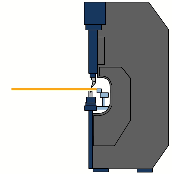
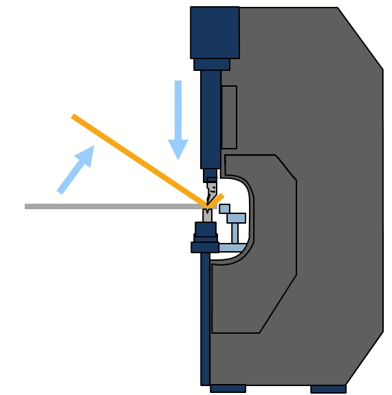
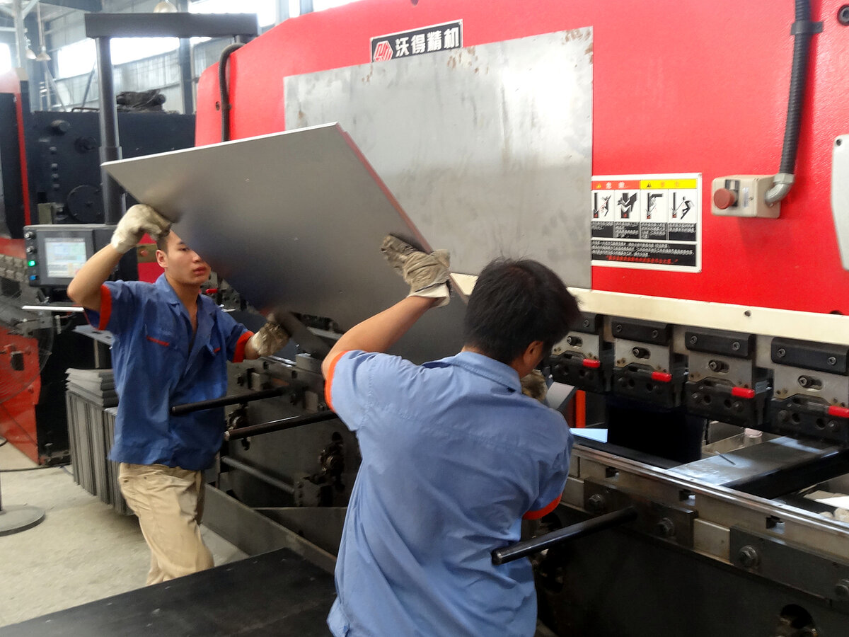
Bending sequence
Press brake
During the bending sequence the blank is positioned outside the machine. The operator holds and supports the weight of the blank. For bending the upper ram moves down into the lower die. Both sides of the part move up and leave the plane. A linear ram movement results in the bend angle. Sequence requires experienced operators.
- Operator needs to lift/support/hold the part (quality problems due to fatigue)
- Experienced, well trained operator required (problem finding skilled operators)
- Health (shoulder problems) and safety are critical
- Large/cumbersome or heavy parts require multiple operators (high costs per part)
- Slow cycle times (high costs per part)
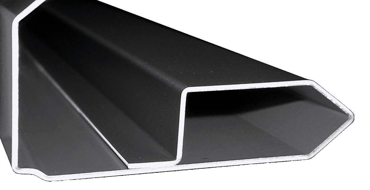
Machine setup
Folding
Folding machines can bend all angles with a single set of tools. The machine automatically adjusts to the material thickness. Higher automated folding machines come with an automatic tool changer.
- Universal tools (reduced setup effort)
- Usually one set of tools sufficient for all customer parts
- Low investment and operating costs
- Low set-up times allow for small batch sizes (need-based production)

Machine setup
Press brake
Press brake bending typically requires a large number of punches and different applications.
- Different "V" dies for different sheet thicknesses
- Small "V" dies required for short flanges
- Usually a large variety of upper ram geometries are used
- Investment in additional tools over time
- Often long set-up times
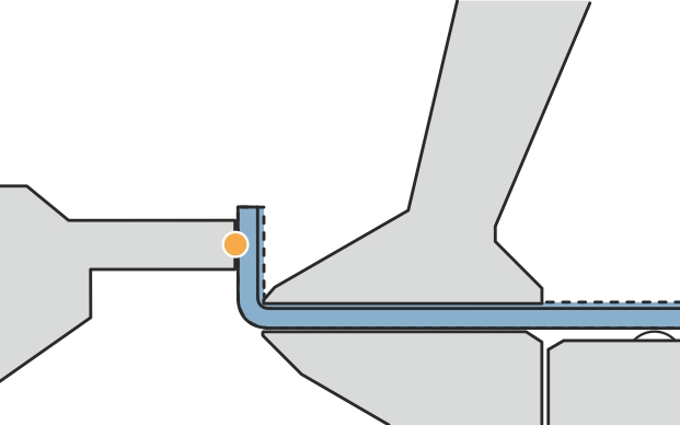
Material thickness tolerances
Folding
During the folding sequence the folding beam tool contacts the outside of the material and moves exactly to the programmed angle.
- The reference side is only the outside of the material
- Exact movement to the programmed angle (high angle accuracy)
- Sheet thickness tolerances do not affect the bend angle
- No angle measuring system required
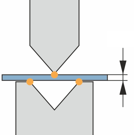
Material thickness tolerances
Press brake
On press brakes, the punch contacts the material from above and the "V" die from below.
- Contact points on both sides of the material
- The bend angle iresults from a linear upper tool movement
- Sheet thickness tolerances lead to angle variances
- Expensive, inflexible angle measuring system required for compensation

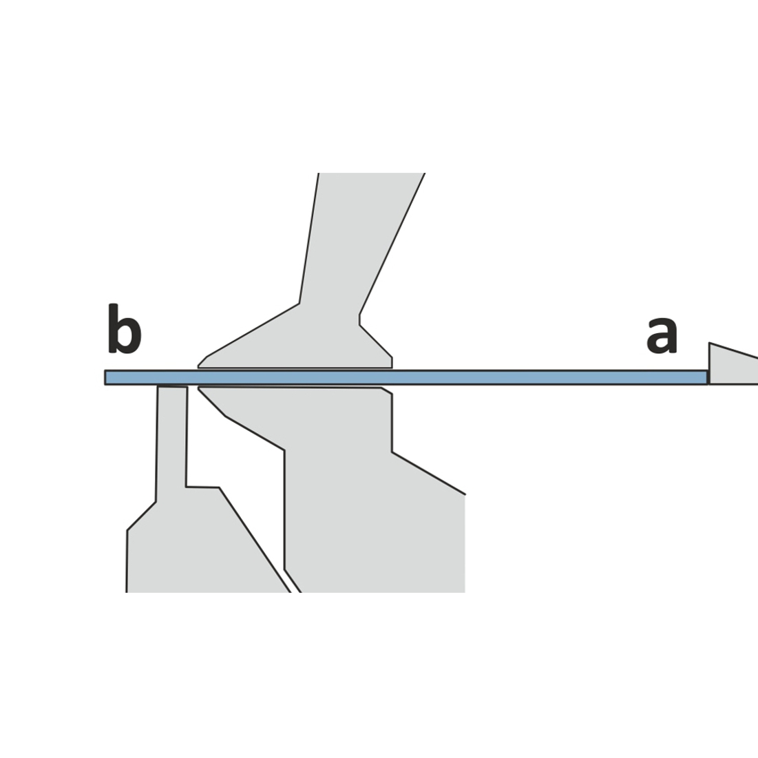
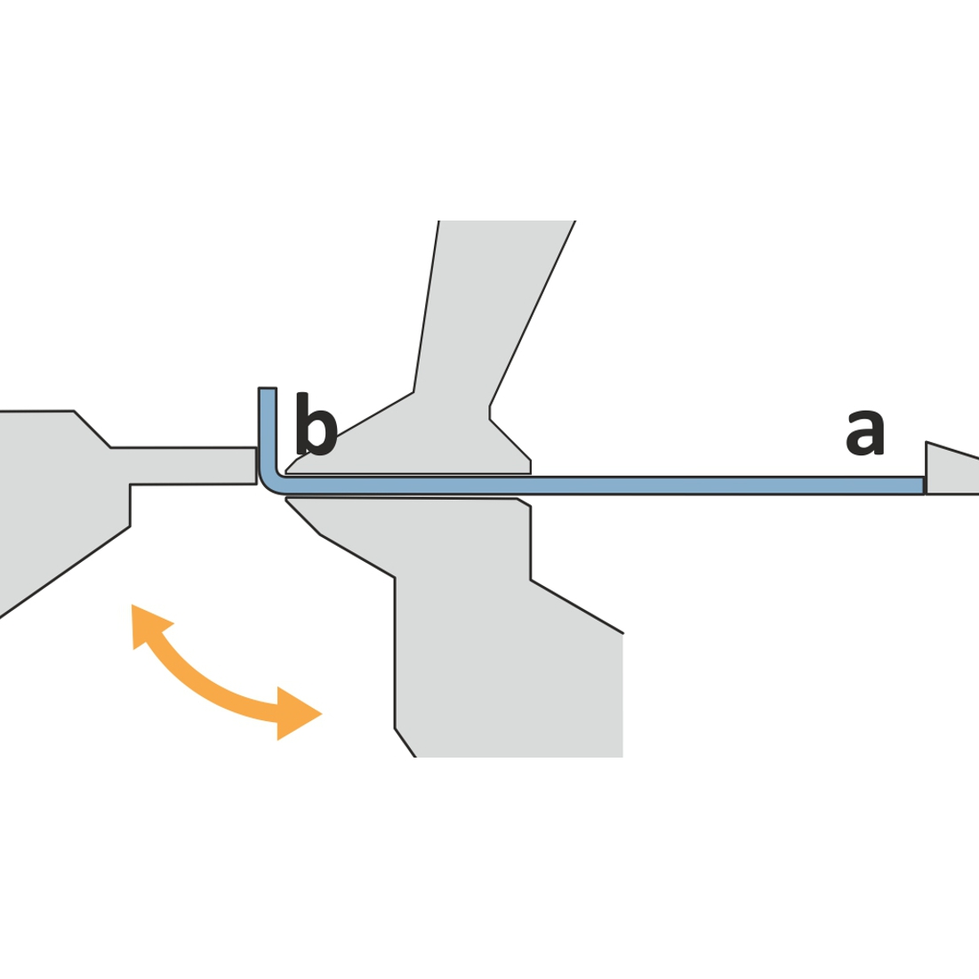
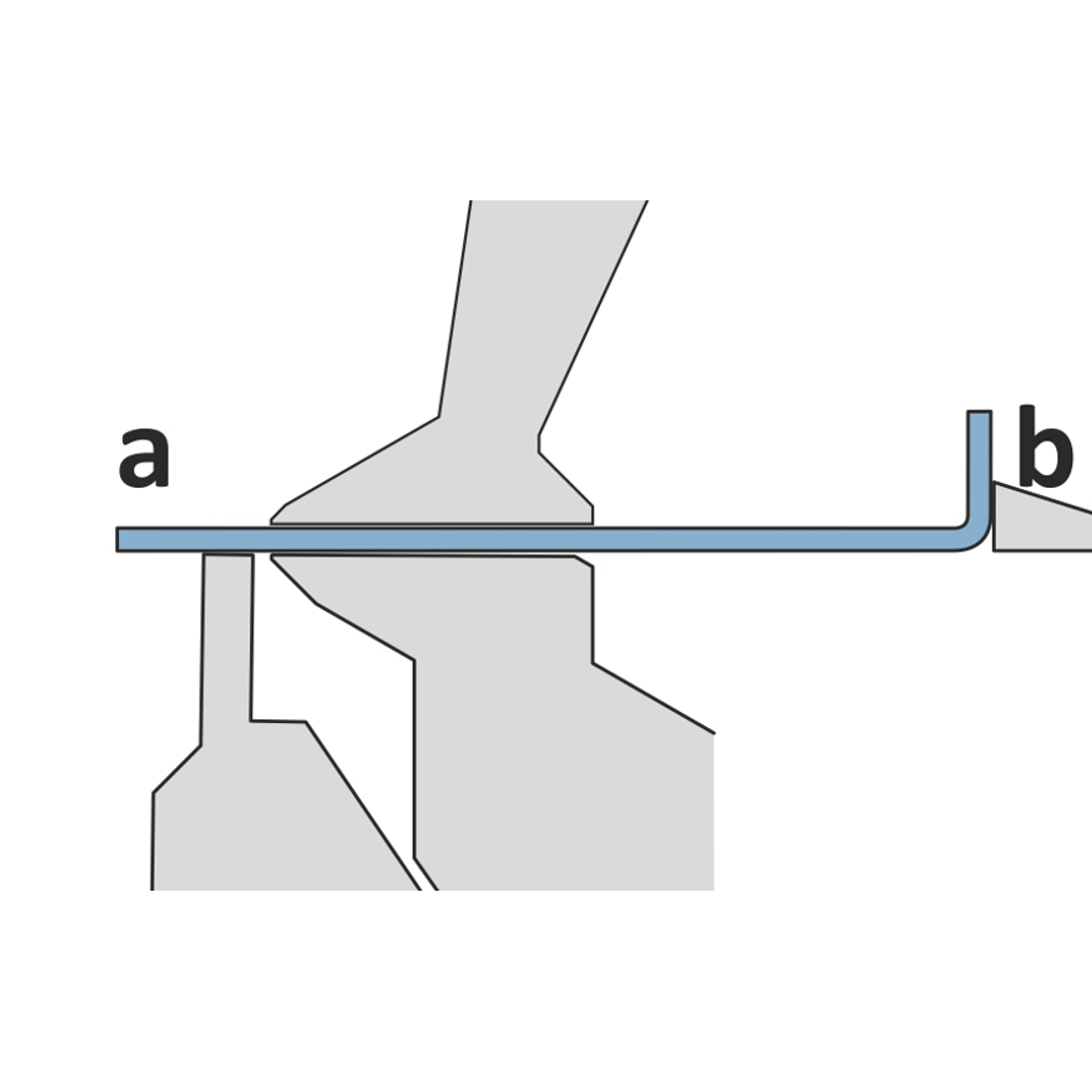
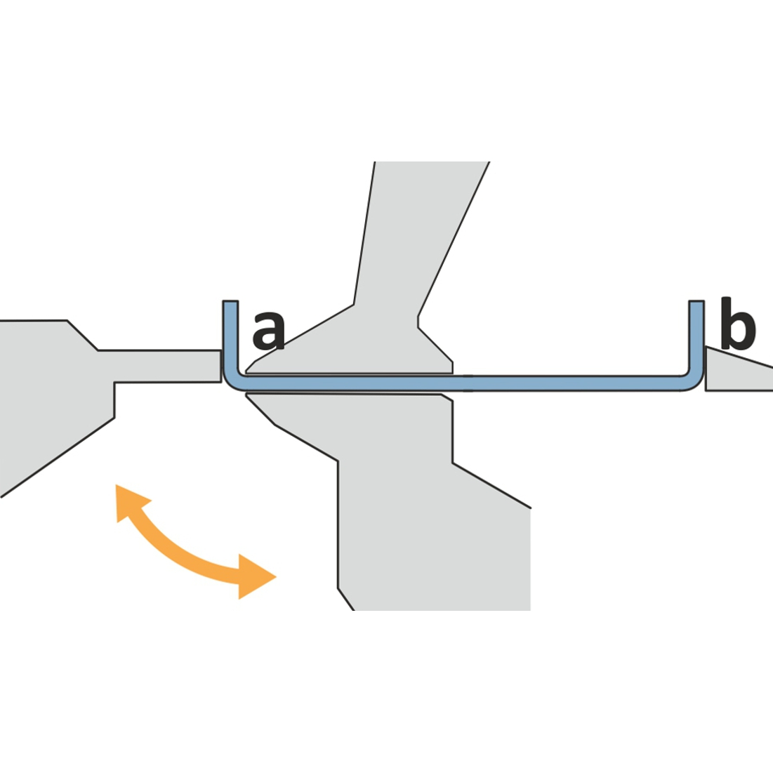
Gauging
Folding
On a folding machine the entire part is inside the machine. Only a short flange stands out of the upper and lower beam tool.
- Gauging of the entire part
- Blanks dimension tolerances show up in the first flange
- The overall panel dimension as well as the opposite flanges are always accurate
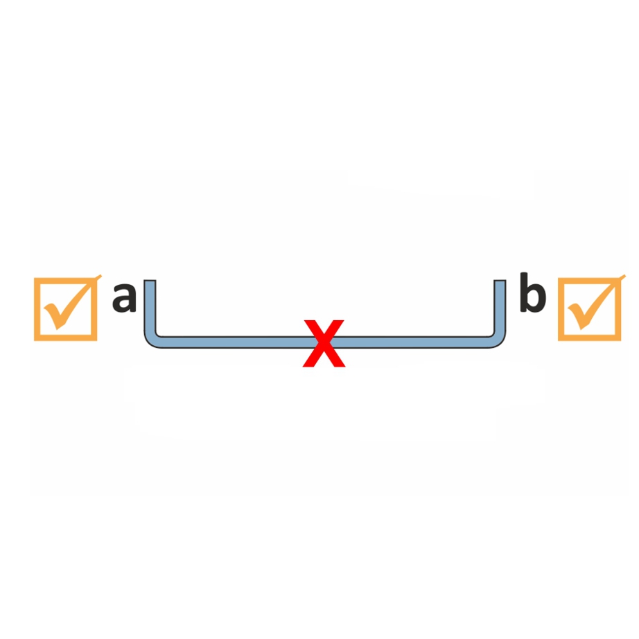
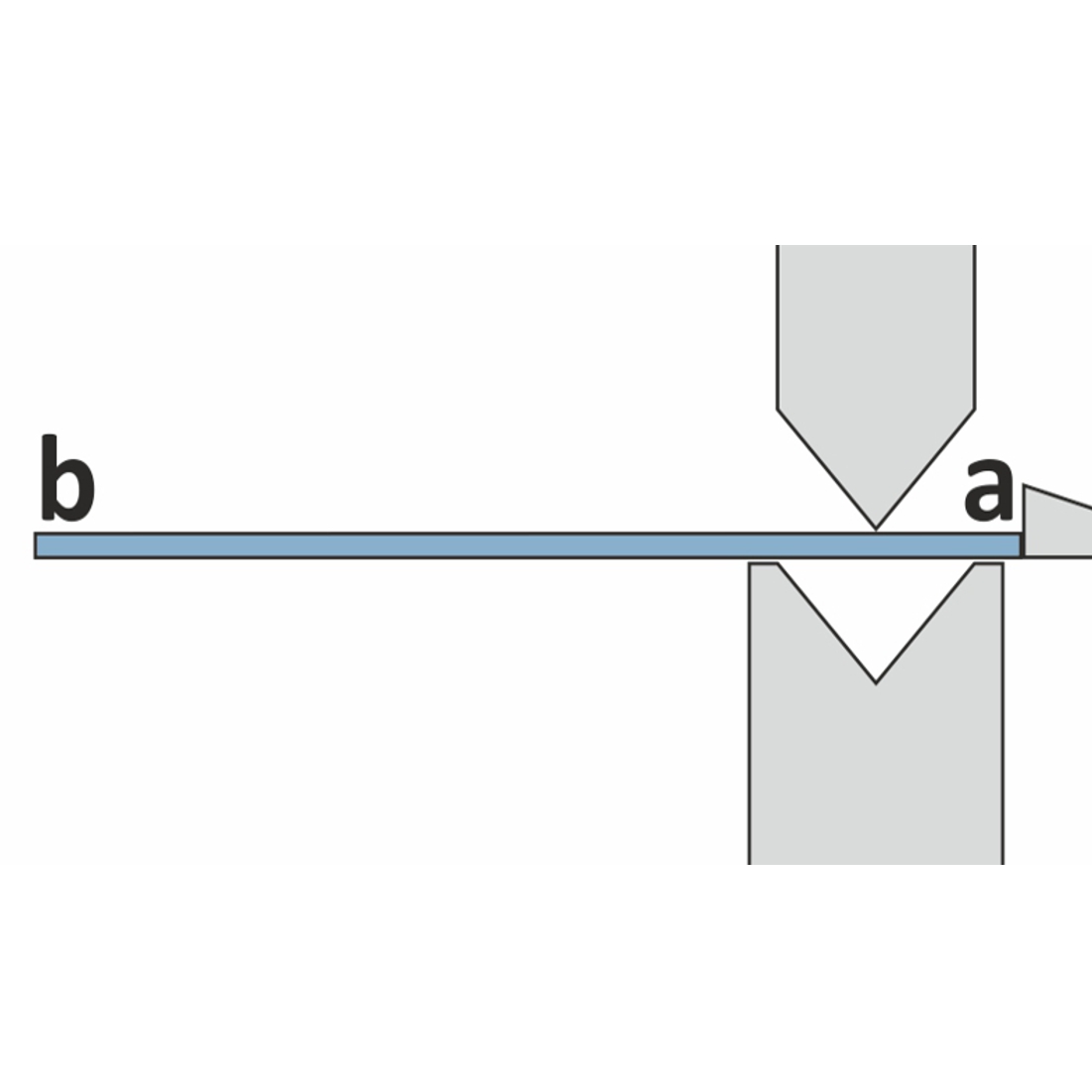
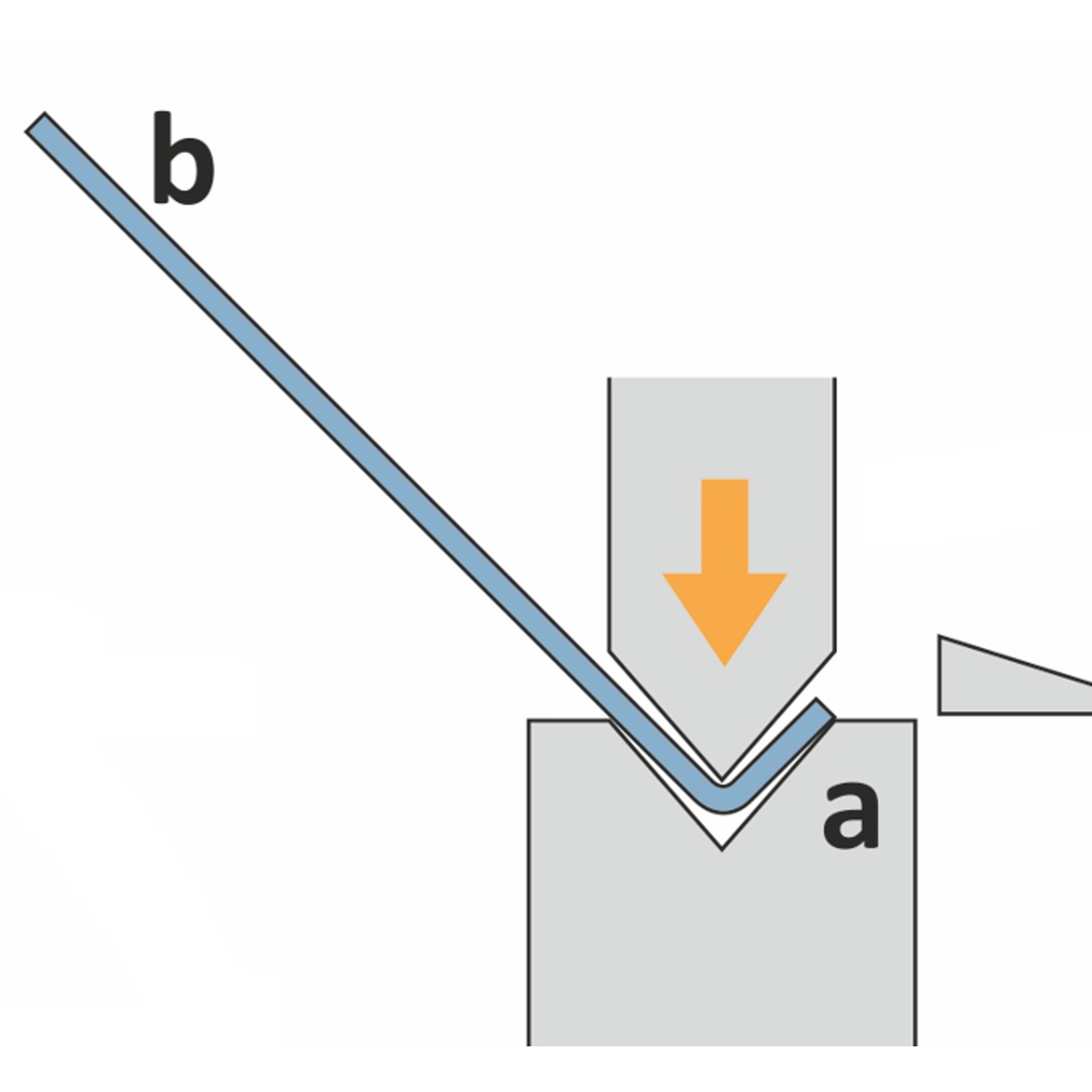
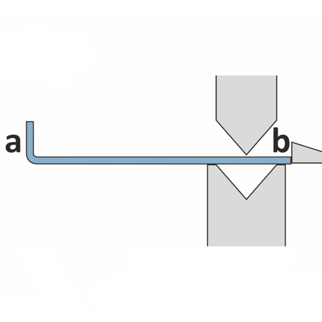
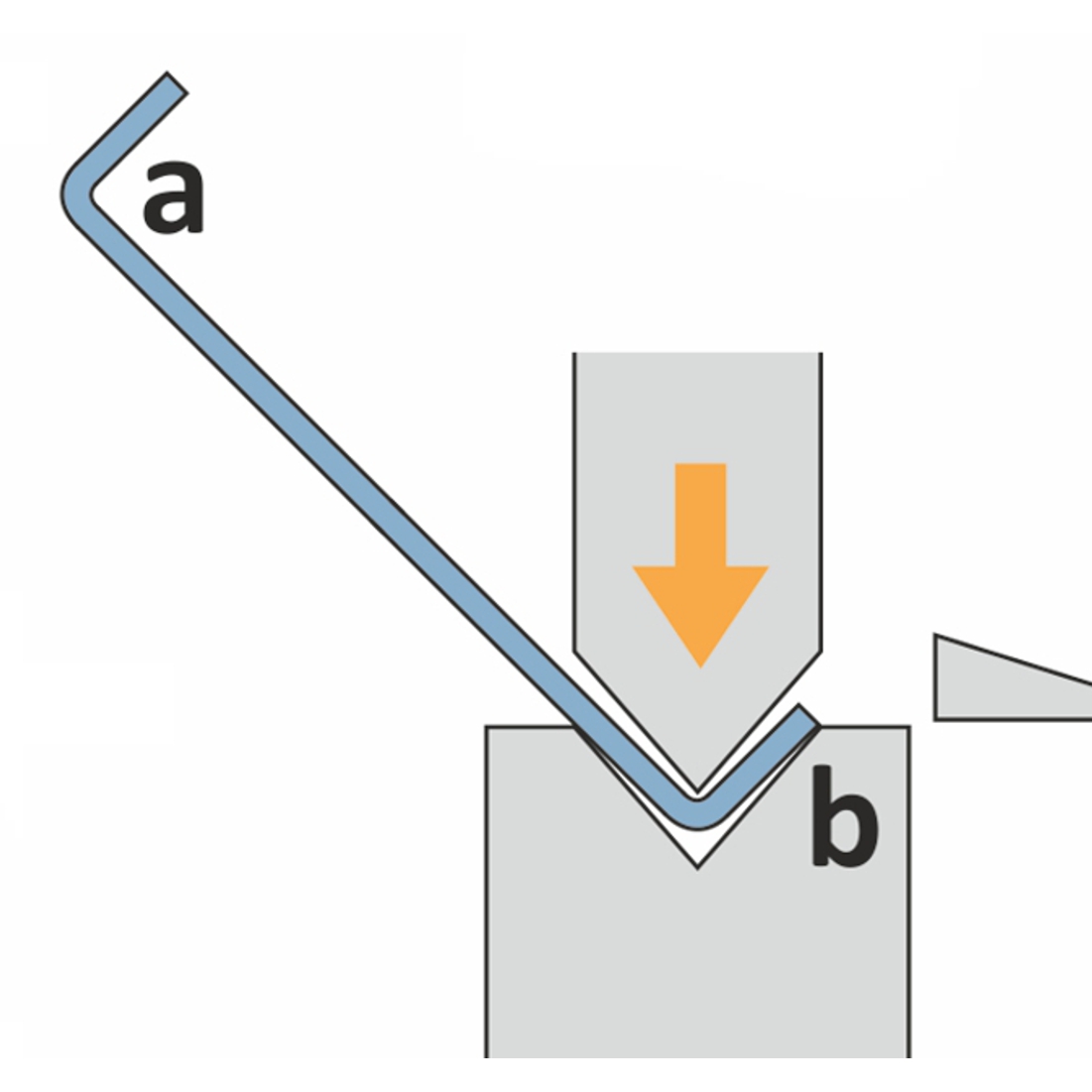
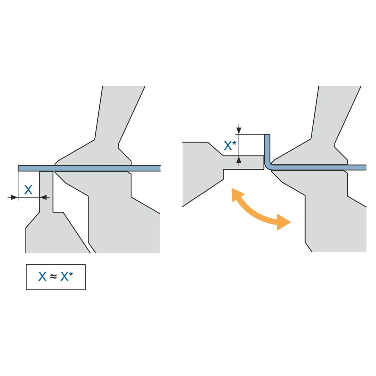
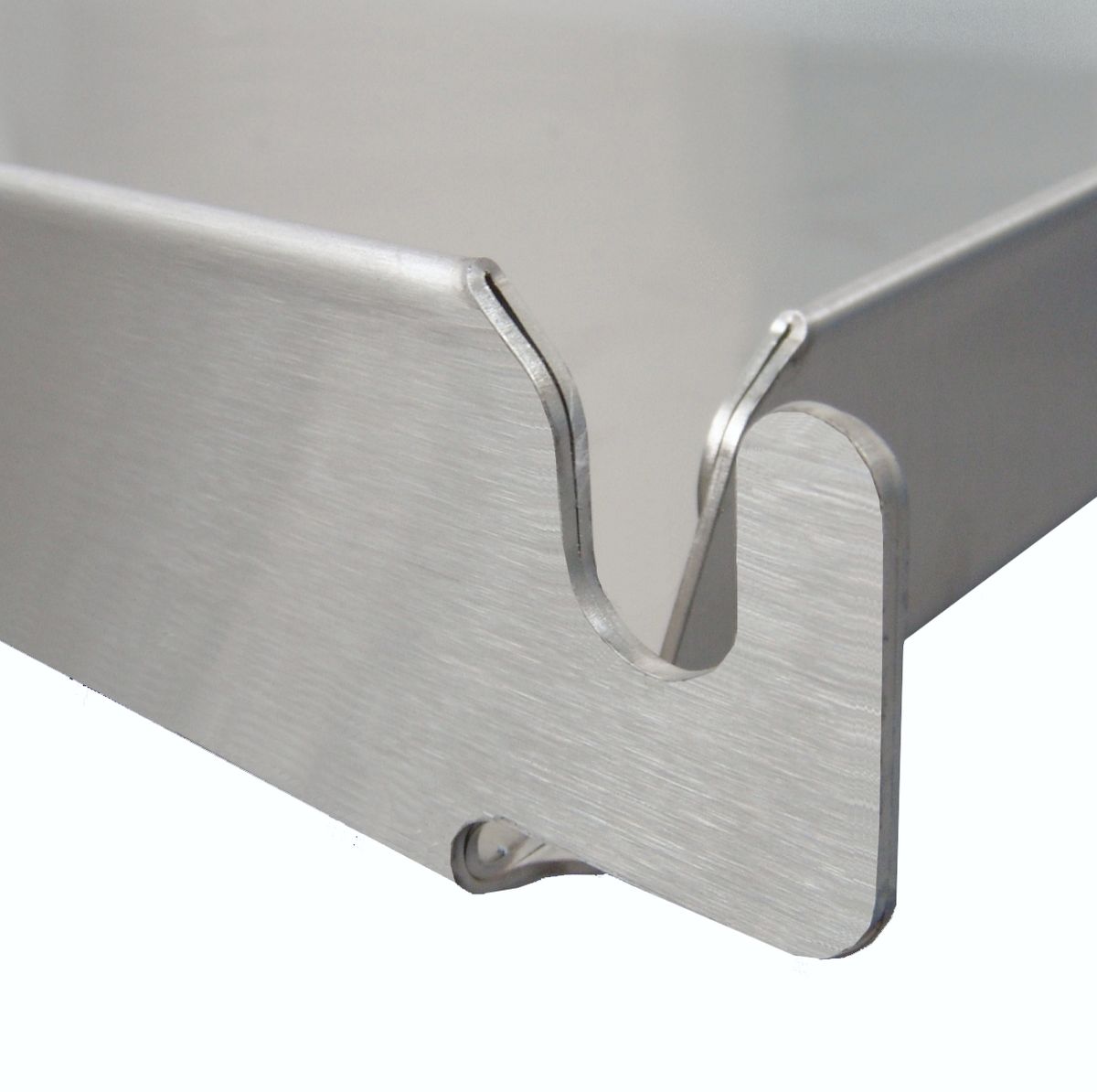
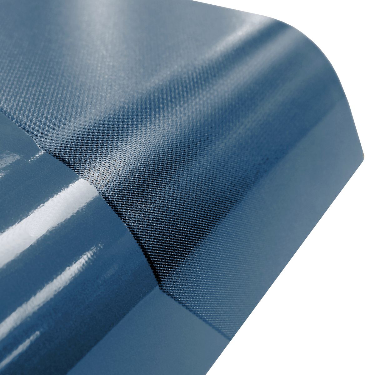
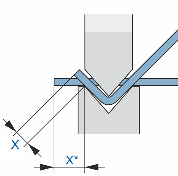
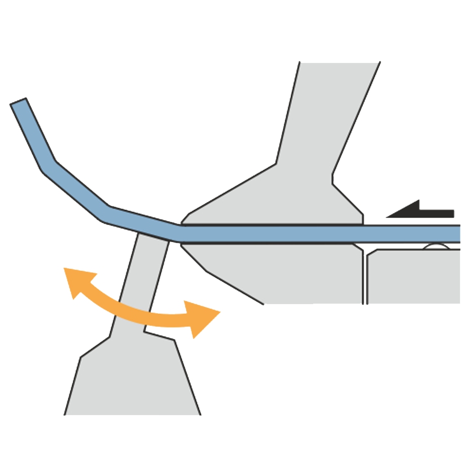
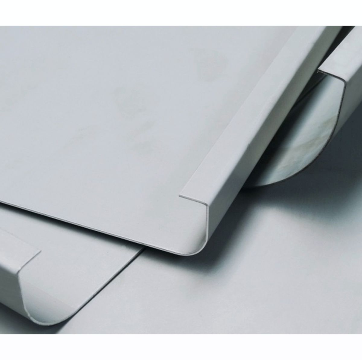
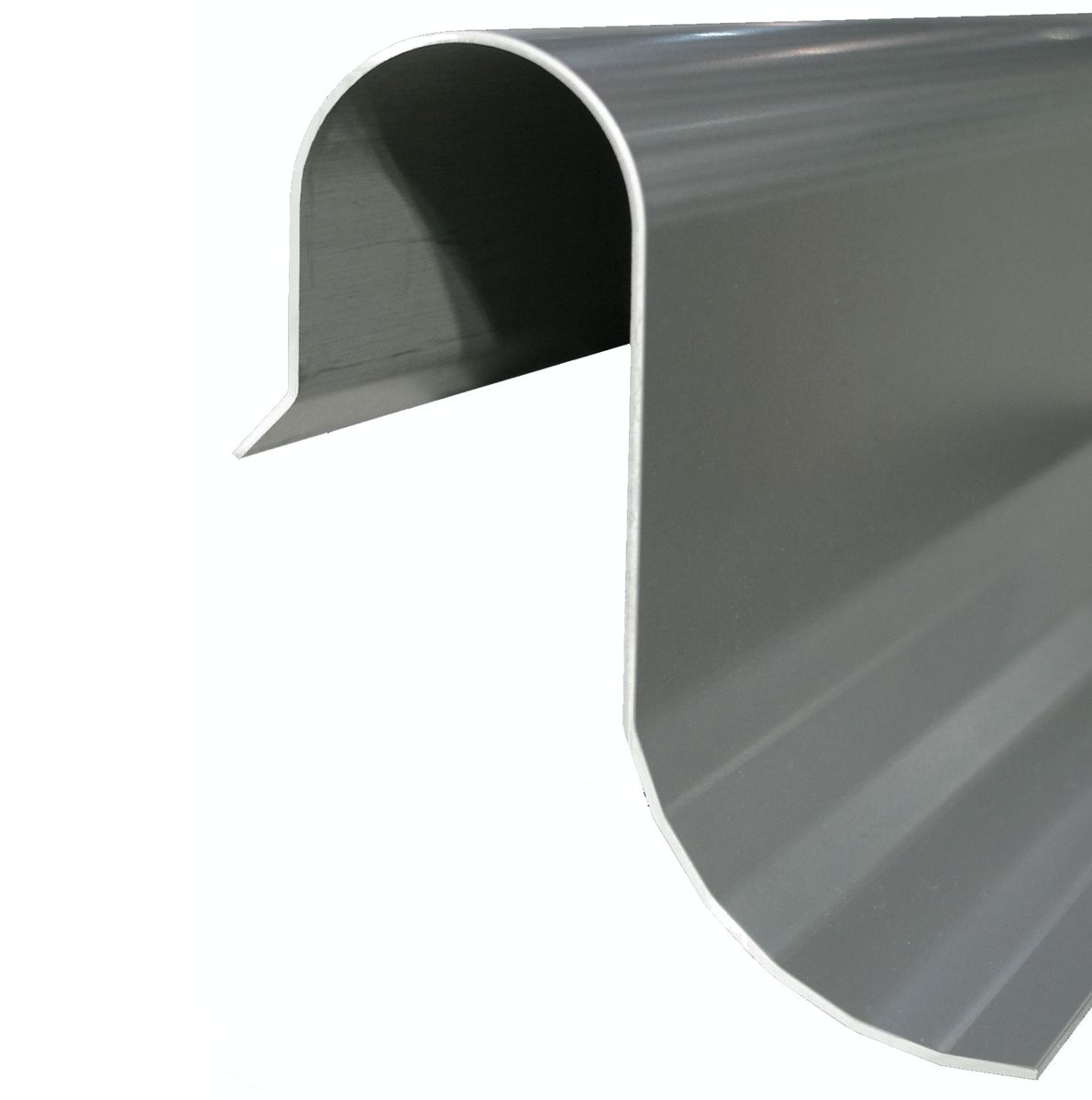
Bending radii
Folding
On folding machines, a radius can be easily created of short bending segments. By using small steps the outside of the radius will be very smooth and the individual steps will not be visible.
- Creation of any radius without special tools
- Bending steps not visible on the outside
- Part rests on the table
- Fast bending cycles